
Wafer Expanding Device, Component Feeder, and Expanding Method for Wafer Sheet

a technology of expanding device and expanding method, which is applied in the direction of metal working apparatus, printed circuit manufacturing, manufacturing tools, etc., can solve the problems of component damage and disturbed component feeding, and achieve the effect of enhancing heating efficiency, reducing the amount of heated air, and reducing the time necessary

Active Publication Date: 2008-01-17
PANASONIC CORP
View PDF5 Cites 10 Cited by
  • Summary
  • Abstract
  • Description
  • Claims
  • Application Information

AI Technical Summary

Benefits of technology

[0048] According to the first aspect of the present invention, at the time of the slack removal processing for removing the slack, which are generated on the wafer sheet due to the expansion, by heating blow from the heating blower device, positioning the wafer feeding plate at a height position between the plate feeding height position and the second height position with the plate up / down device allows a distance between the upper end portion of the expanding ring and the lower face of the wafer sheet to be sufficiently smaller than the distance in the case where the wafer feeding plate is positioned at the plate feeding height position. Therefore, it becomes possible to reduce an amount of heated air supplied by the heating blower device and leaking from an interval between the upper end portion of the expanding ring and the lower face of the wafer sheet, enhance heating efficiency to heat the wafer sheet and reduce a time necessary for the slack removal processing. Further, it becomes possible to make the temperature of the wafer sheet almost uniform, thereby allowing reduction of uneven heating.
[0049] Moreover, the height position is so set as to avoid the contact between the wafer sheet and the upper end portion of the expanding ring at least when the slack removal processing is completed, which can reliably prevent the shrinking operation of the wafer sheet by the heating blow from being disturbed by the contact with the upper end portion of the expanding ring. Therefore, it becomes possible to reduce uneven heating and uneven shrinkage and to perform the slack removal processing efficiently and evenly.
[0050] Moreover, according to another aspect of the present invention, a gap between the upper end portion of the expanding ring and the wafer sheet is determined in consideration of suppression of leakage of heated air supplied by the heating blower device, which makes it possible to reliably implement the efficient and uniform slack removal processing.
[0051] Moreover, the upper end portion of the expanding ring has a shape bent toward the inside of the ring, which allows further suppression of leakage of the heated air from the gap.
[0052] Moreover, the smaller the gap is, the more efficient the heating becomes because leakage of the heated air from the gap can be suppressed. However, in the case where the upper end portion of the expanding ring comes into contact with the wafer sheet during execution of the slack removal processing (from the start to the end of processing), there are such problems that heat is drawn from the heated wafer sheet to the expanding ring, resulting in processing in longer time and that the wafer sheet during the shrinkage process is caught on the upper end portion of the expanding ring and the shrinkage is disturbed. Consequently, at least when the slack removal processing is completed, a gap in the range of 0.2 to 1.5 mm or a gap corresponding to the gap of this size range is provided.
[0053] Moreover, such a third height position is so set as to serve also as a height position for allowing tray feed components to be fed from the tray feeding plate, which makes it possible to provide a component feeder capable of implementing the effects achieved by the respective aspects while simplifying their structures without the necessity of setting a new height position in the plate placement device.

Problems solved by technology

However, when such expansion is applied, even the wafer sheet 508 which can elastically deform to some degree cannot perfectly regain its original state and resultingly having some slacks.
With the presence of such slacks, shaking and vibration are transmitted to the wafer feed components 502 remaining on the wafer sheet 508 during transportation of the wafer feeding plate 506, which may result in component damages.
Moreover, there are cases in which the wafer feeding plate 506 is housed in a magazine cassette and the like once the wafer feed components 502 on the wafer sheet 508 are removed, and if the wafer sheet 508 has slacks in such cases, the wafer sheet 508 may be caught on a transportation unit and the like, which may cause a problem that smooth component feeding is disturbed.

Method used


Image

  • Wafer Expanding Device, Component Feeder, and Expanding Method for Wafer Sheet
  • Wafer Expanding Device, Component Feeder, and Expanding Method for Wafer Sheet
  • Wafer Expanding Device, Component Feeder, and Expanding Method for Wafer Sheet

Examples


first embodiment

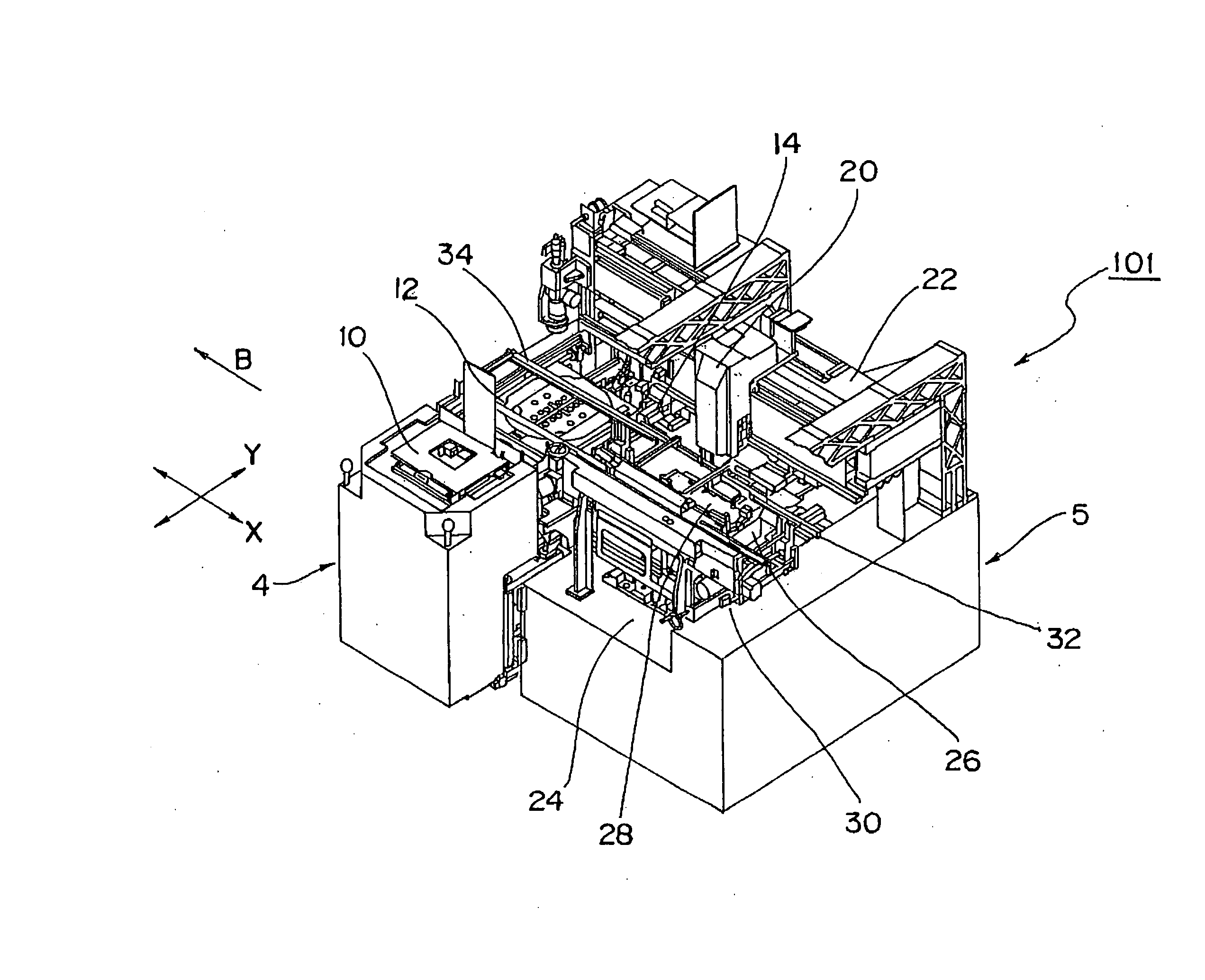
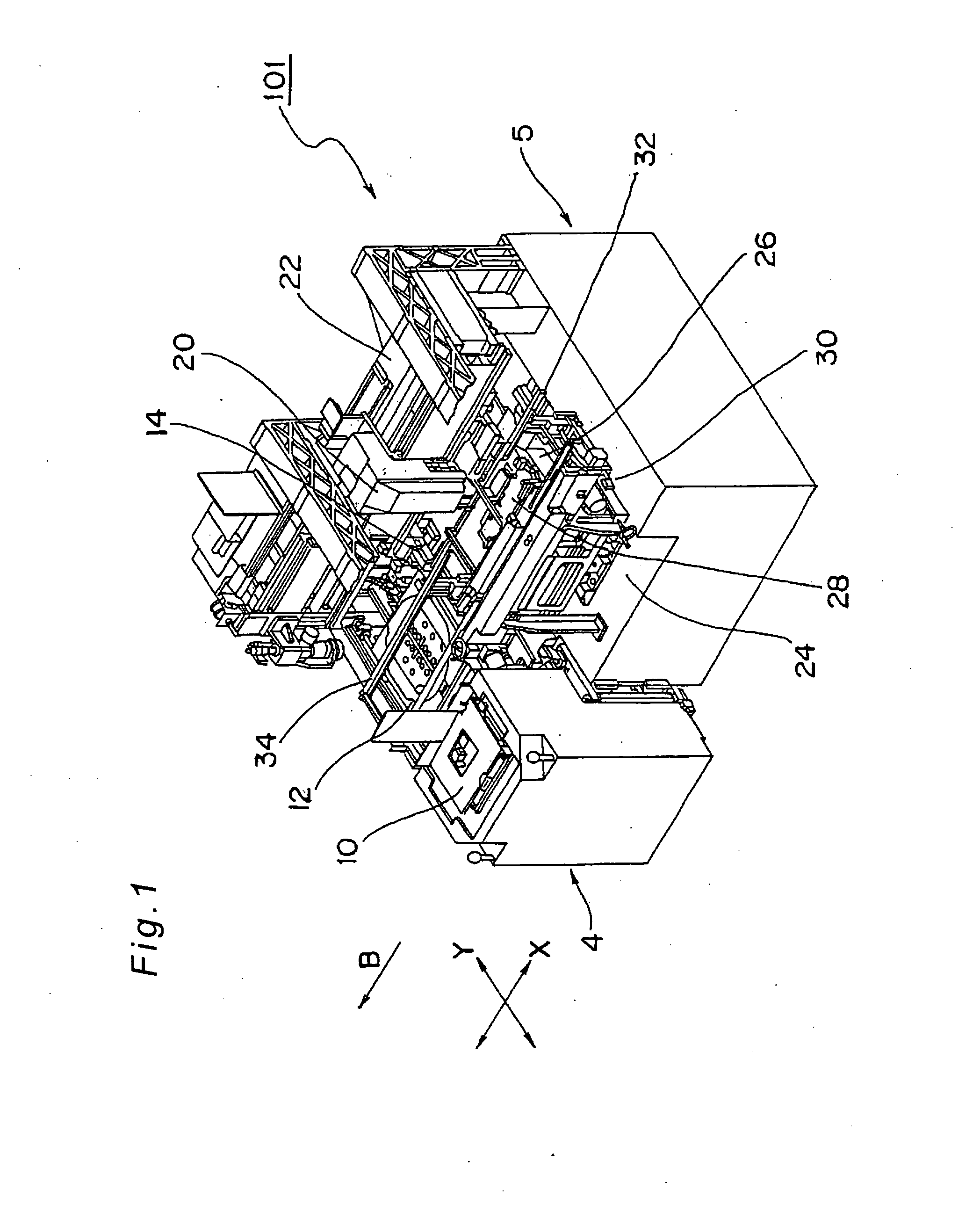
[0089]FIG. 1 is an external perspective view showing an electric component mounting apparatus 101 exemplifying a component mounting apparatus having a component feeder 4 exemplifying a component feeder for mounting components fed from the component feeder 4 on a board according to a first embodiment of the present invention. Before the specific structure and operation of the component feeder 4 will be described, the overall structure and operation of the electric component mounting apparatus 101 having such a component feeder 4 will be described with reference to FIG. 1.

[0090] (Electric Component Mounting Apparatus)

[0091] As shown in FIG. 1, the electric component mounting apparatus 101 is an apparatus which executes mounting operation for mounting electric components 2 exemplifying components such as chip components and bare IC chips on the board, and which mainly includes a component feeder 4 for feedably housing a plurality of the electric components 2 and a mounting section 5 ...

second embodiment

[0168] It is to be noted that the present invention is not limited to the embodiment disclosed, and may be embodied in various forms. For example, a component feeder according to a second embodiment of the present invention is different from the component feeder 4 in the first embodiment in the point that two types of plates 6 are handled as wafer feeding plates, and other structures are identical to those in the first embodiment. Therefore, only the different structures will be described with reference to the drawings.

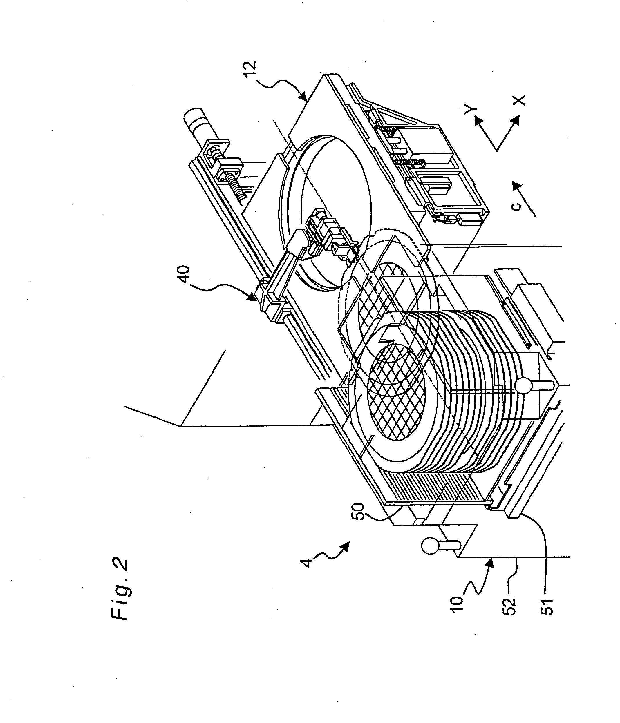
[0169] In the second embodiment, the component feeder 4 in the first embodiment is used as it is. In a magazine cassette 50 included in the component feeder 4, wafer feeding plates 6w for feeding wafer feed components 2w and tray feeding plates 6t for feeding tray feed components 2t are housed in a consolidated state, and further, expanded wafer feeding plates 6f which have an expanded wafer holding ring placed on its upper face which is for holding a relatively smal...


PUM

PropertyMeasurementUnit
Lengthaaaaaaaaaa
Lengthaaaaaaaaaa
Heightaaaaaaaaaa

Abstract

In slack removal processing for removing slack generated on a wafer sheet by heating blow, a wafer feeding plate is positioned at a height position between a first height position and a second height position. This makes it possible to decrease a gap between an upper end portion of an expanding ring and a lower face of the wafer sheet and allows efficient and uniform processing. Moreover, setting the height position so as to avoid the contact between the wafer sheet and the upper end portion of the expanding ring at least when the slack removal processing is completed reliably prevents shrinking operation of the wafer sheet from being disturbed by the contact between the wafer sheet and the upper end portion.

Description

TECHNICAL FIELD [0001] The present invention relates to a wafer expanding device, a component feeder and a wafer sheet expanding method for radially stretching a wafer sheet, on which a plurality of wafer feed components formed through dicing of a wafer is attached, over a wafer feeding plate which holds the wafer sheet for expansion and for making the respective wafer feed components feedable from the wafer sheet. BACKGROUND ART [0002] Wafer expanding devices of this kind have conventionally been known in various structures (e.g., Patent Document 1). The wafer expanding operation by such conventional wafer expanding devices will be described with reference to schematic views shown in FIG. 28A and FIG. 28B. [0003] As shown in FIG. 28A, a wafer feeding plate 506 holds a wafer sheet 508 on the top face of which a plurality of wafer feed component 502 formed through dicing of a wafer are attached, and in this held state, the wafer sheet 508 is kept in an almost horizontal posture witho...

Claims


Application Information

Patent Timeline
IPC IPC(8): H05K3/36H01R43/00B23P19/00H01L21/00H01L21/301H01L21/68
CPCH01L21/67132Y10T29/49144Y10T29/53265Y10T29/49126Y10T29/4913Y10T29/53187Y10T29/49117
Inventor NARITA, SHORIKIHIRATA, SHUICHITSUJISAWA, TAKAFUMIMIYAZAKI, HIROKUNISHIDA, SATOSHI
Owner PANASONIC CORP
Learn More