
Glitch-free clock switcher

a clock switcher and clock technology, applied in the direction of instruments, generating/distributing signals, pulse techniques, etc., can solve the problems of circuits that are not truly glitch free, add to circuit cost and complexity, etc., and achieve no short cycling output and low power consumption

Inactive Publication Date: 2008-01-17
EASTMAN KODAK CO
View PDF18 Cites 8 Cited by
  • Summary
  • Abstract
  • Description
  • Claims
  • Application Information

AI Technical Summary

Benefits of technology

The present invention provides a circuit that can switch between different clock signals without causing any glitches. The circuit uses an asynchronous logic circuit and a combinational logic clock output circuit. The output circuit only generates a new clock signal when it detects a falling edge of the current clock signal and a falling edge of the new clock signal. This results in a more reliable and accurate switching of clock signals.

Problems solved by technology

Examples such attempts are found in U.S. Pat. Nos. 6,774,681 B2; 6,784,699 B2; and 6,275,546 B1 which typically require excessive amount of control signals to function and / or have very high gate counts, e.g. 41 or higher, which adds to the cost and complexity of the circuits.
While effective to some extent, the circuit is not truly glitch free with an asynchronous clock select signal.
The problem is inherent with the use of D flip flops in the circuit which are constrained to change state only on the input clock edge.

Method used


Image

  • Glitch-free clock switcher
  • Glitch-free clock switcher
  • Glitch-free clock switcher

Examples


Embodiment Construction

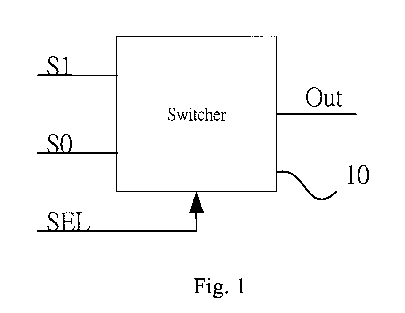
[0017]Referring to FIG. 1, the basic 2-1 clock switching circuit 10 is shown having a clock select input signal SEL and a pair of clock input signals S1 and S0. The clock signals are of different frequencies and are asynchronous to each other. For operation of the circuit, it is not necessary to designate which of the clock signals is the higher frequency signal. Clock select signal SEL is a simple bi-state selection and the clock selection transition may be asynchronous with the two clock signals.

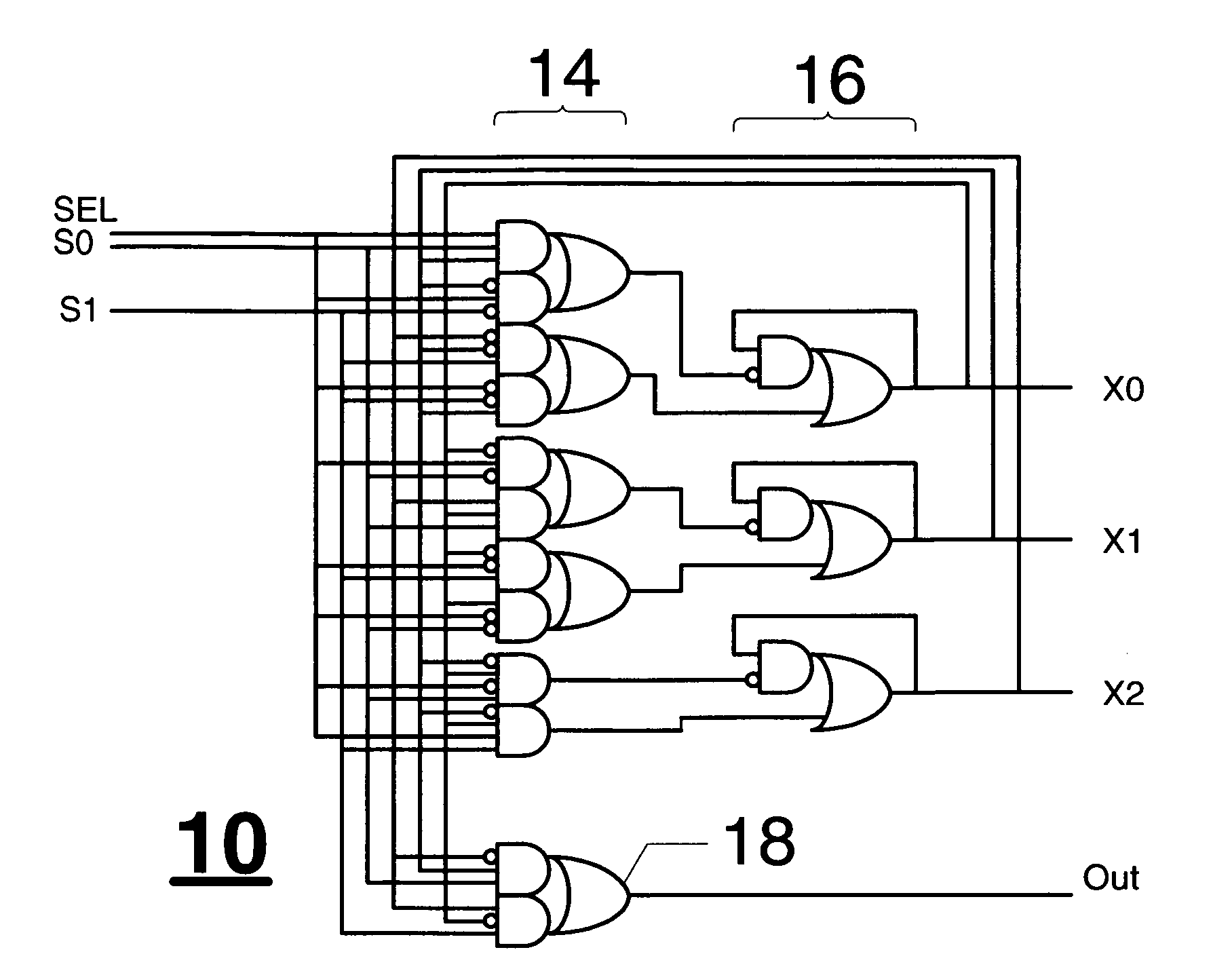
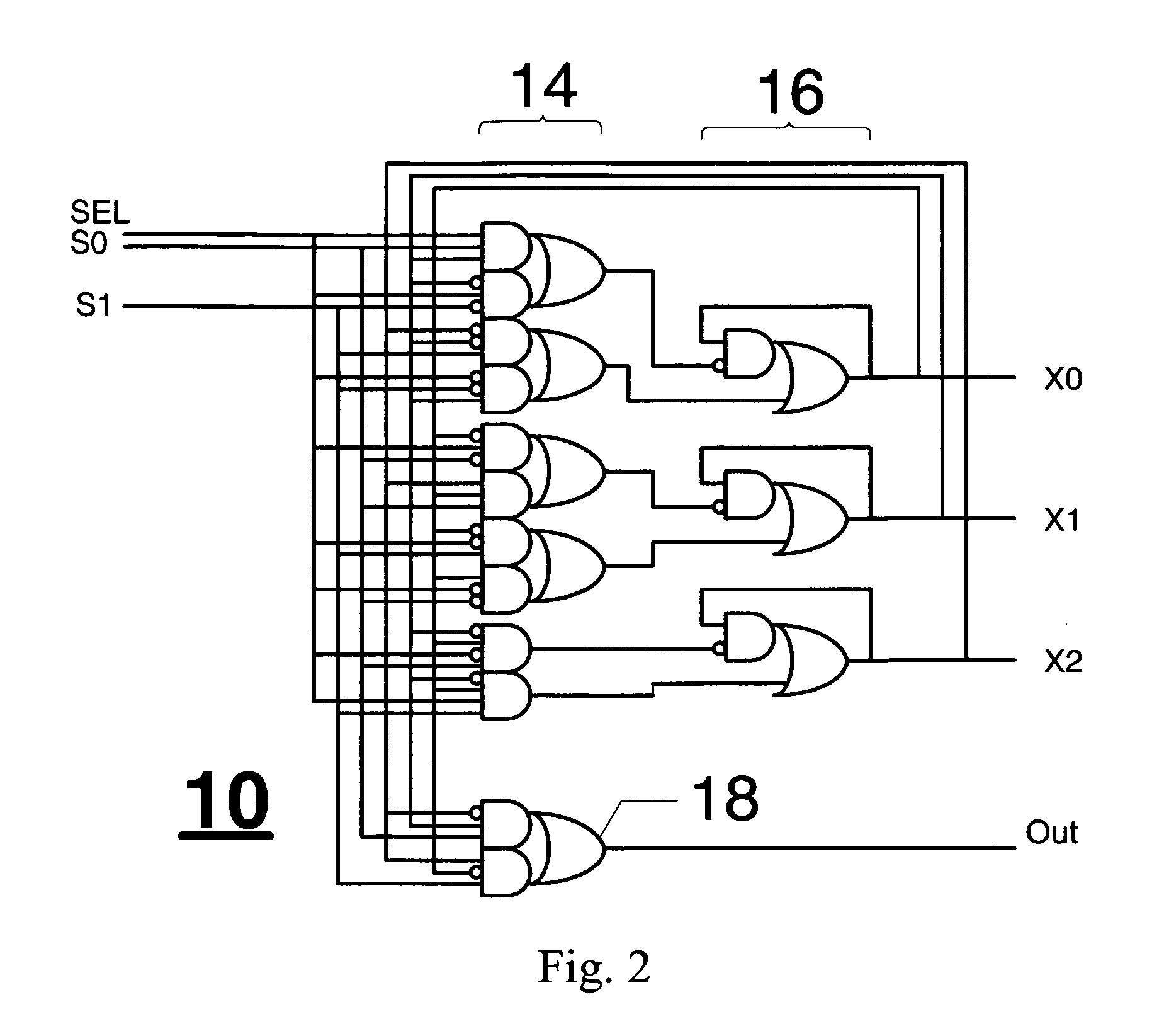
[0018]FIG. 2 illustrates a presently preferred embodiment of the invention configured in accordance with the design process described later. In this embodiment, switching circuit 10 comprises an asynchronous, sequential logic circuit having, as inputs, clock select signal SEL, and clock signals S0 and S1. Consistent with sequential logic circuit design, circuit 10 includes an input logic stage 14 and an operating state machine 16. In addition to the clock select and clock signals, the inpu...


PUM


Abstract

A glitch-free, clock switching circuit in which an asynchronous, sequential logic circuit has as inputs a clock select signal and a pair of clock signals. A plurality of operating state variable signals are generated in the sequential logic circuit in response to transitions in the input signal. A combinational logic clock output circuit is responsive to the input clock signals and predetermined ones of the operating state variable signals for outputting a newly selected clock signal only when said predetermined operating state variable signals indicate the sensing of a falling edge of the currently outputted clock signal followed by a falling edge of the newly selected clock signal.

Description

FIELD OF THE INVENTION[0001]The invention relates generally to the field of digital clock switching circuits and, in particular, to a glitch-free clock switcher circuit that enables selection of an output clock signal from a plurality input clock signals of different frequencies without resulting in the output of arbitrarily short clock pulses.BACKGROUND OF THE INVENTION[0002]In digital circuits, clock sources provide pulsed timing signals which allow for appropriate timing and ordering events occurring within the circuits. It is desirable in many of those circuits to allow the clock source for the circuit to be switched from time to time between any of a plurality of clock sources. It is important when switching clock signals to avoid outputting arbitrarily short pulses that are shorter than any of the clock source signals, referred to commonly as “glitches” in order to maintain proper operation of the digital circuits.[0003]Numerous attempts have been made to provide clock switche...

Claims


Application Information

Patent Timeline
Patent Type & Authority Applications(United States)
IPC IPC(8): G06F1/08
CPCG06F1/08
Inventor CHEUNG, HUNG K.
Owner EASTMAN KODAK CO
Learn More