
High-Speed Signal Testing System Having Oscilloscope Functionality

a signal testing and high-speed technology, applied in the direction of frequency-division multiplex, instruments, transmission monitoring, etc., can solve the problems of long-term problems, limited bandwidth, and modification of the basic equipment architecture that limits scalability, and achieves difficult calibration, bandwidth limitation, and large area consumption of delay line circuitry

Inactive Publication Date: 2008-01-17
DFT MICROSYST
View PDF71 Cites 16 Cited by
  • Summary
  • Abstract
  • Description
  • Claims
  • Application Information

AI Technical Summary

Benefits of technology

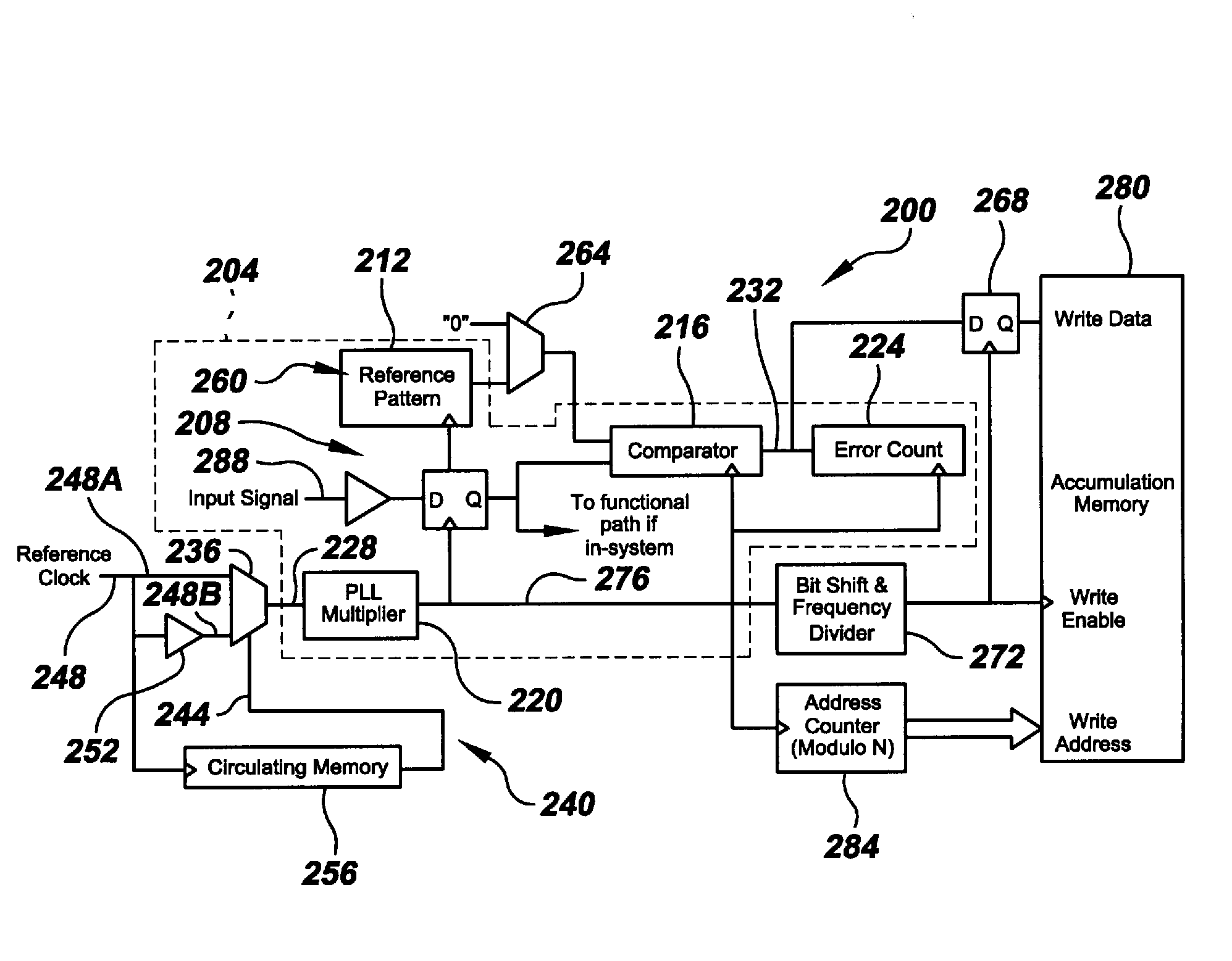
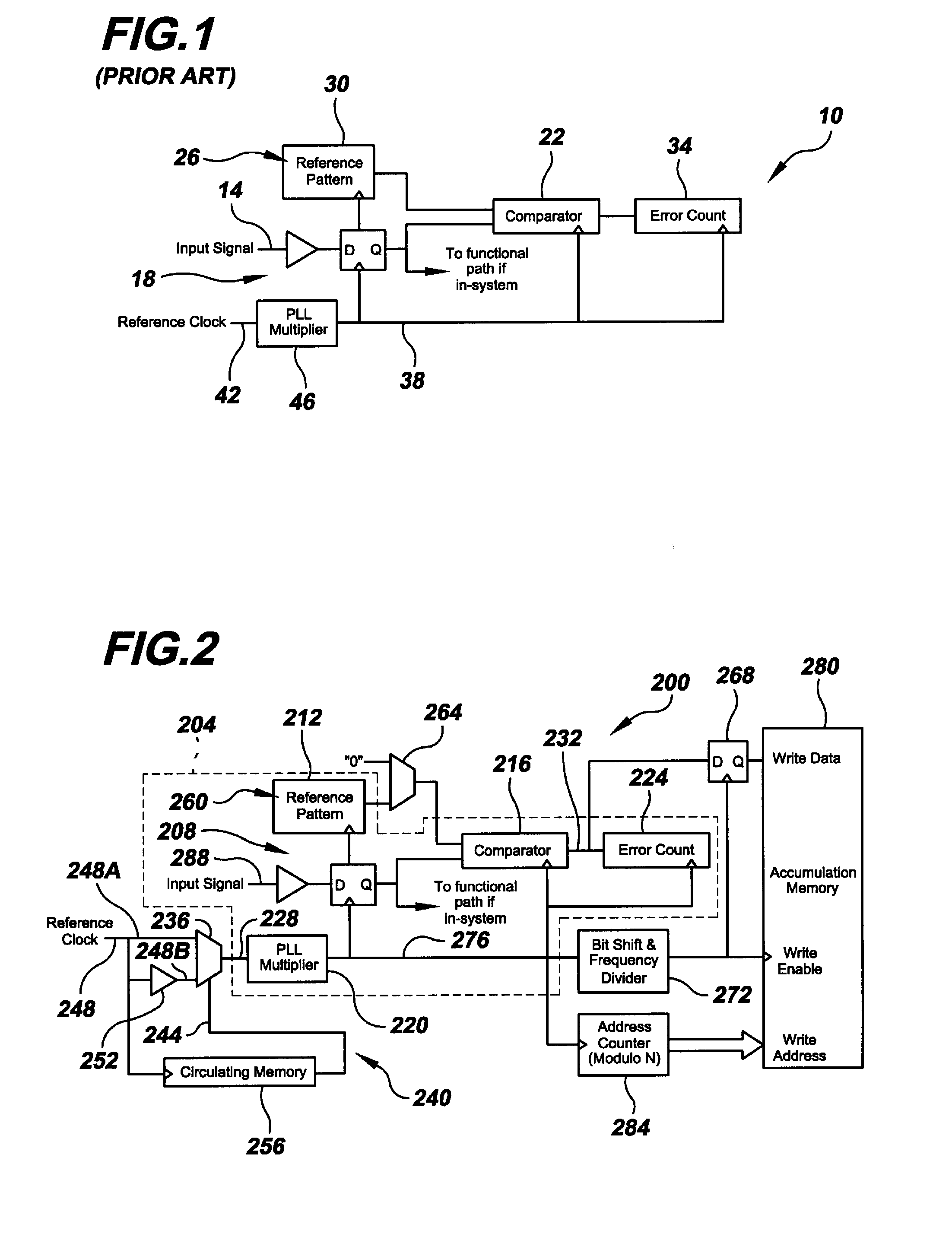
[0007]One aspect of the present invention is a system for testing a high-speed repeating data signal, comprising: a time-base generator responsive to a reference clock signal so as to generate a high-speed repeating signal; a one-bit voltage digitizer for digitizing the high-speed repeating data signal into a digitized signal as a function of the high-speed repeating signal; a digital comparator for comparing the digitized signal to a selected digital value and outputting comparator results as a function of the high-speed repeating signal; a bit-shift and frequency-divider block responsive to the high-speed repeating signal so as to produce a slowed clock signal; a sub-sampler for sub-sampling the comparator results as a function of the slowed clock signal so as to output sub-sampled results; a modulo N address counter for providing write addresses as a function of the high-speed repeating signal; and an accumulation memory for storing ones of the sub-sampled results as a function of the slowed clock signal and corresponding respective ones of the write addresses.
[0008]Another aspect of the present invention is a system for testing a high-speed repeating data signal, comprising: oscilloscope circuitry that includes: a time-base generator responsive to a reference clock signal so as to generate a high-speed repeating signal; a one-bit voltage digitizer for digitizing the high-speed repeating data signal into a digitized signal as a function of the high-speed repeating signal; a reference pattern memory for storing a reference bit pattern having a length B; a selector for selecting between the reference bit pattern and a constant bit value so as to output a selected digit...

Problems solved by technology

Poor analog parameters such as too long a rise time or too small a voltage swing may result in long term issues that are not uncovered using quick pattern tests.
Such failures can be caused by systematic phenomena that manifest themselves in waveform shape or timing jitter.
However, given the contradicting requirements between pattern testing and analog parametric testing, creating such dual-function equipment entails intricate modifications to the basic architecture of the equipment that limits scalability.
The delay line circuitry is area-consuming, bandwidth-limited, and difficult to calibrate.
It becomes unmanageable when several test channels are required, as is the case in modern applications or applications in which the pattern tester is integrated within a system.
Specifically, logic testing merely requires a voltage comparator at the front end of the equipment whereas a measurement such as an eye diagram requires a more complex circuit.
This approach is again complicated and difficult to implement at very high speeds.

Method used


Image

  • High-Speed Signal Testing System Having Oscilloscope Functionality
  • High-Speed Signal Testing System Having Oscilloscope Functionality
  • High-Speed Signal Testing System Having Oscilloscope Functionality

Examples


Embodiment Construction

[0020]FIG. 1 shows a prior-art digital pattern tester 10 for testing logical integrity of an input signal 14 input into the tester. As mentioned in the Background section above, tester 10 could be part of the design of a high-speed digital communications device (not shown), or it could be a standalone piece of equipment, such as a BERT or logic analyzer. The front-end of tester 10 is a voltage comparator 18 that “slices” the voltage of incoming signal 14 and recovers a logical value from it. The logical value is “1” when the input signal is larger than the voltage threshold of comparator 18 and “0” otherwise. Using a digital comparator 22, the logical value is then compared, bit for bit, to a reference pattern 26 stored in an onboard memory 30. An error counter 34 keeps track of the number of mismatches between the logical values derived from input signal 14 on the one hand and the corresponding respective bits of reference pattern 26 on the other.

[0021]Digital comparator 22 is cloc...


PUM


Abstract

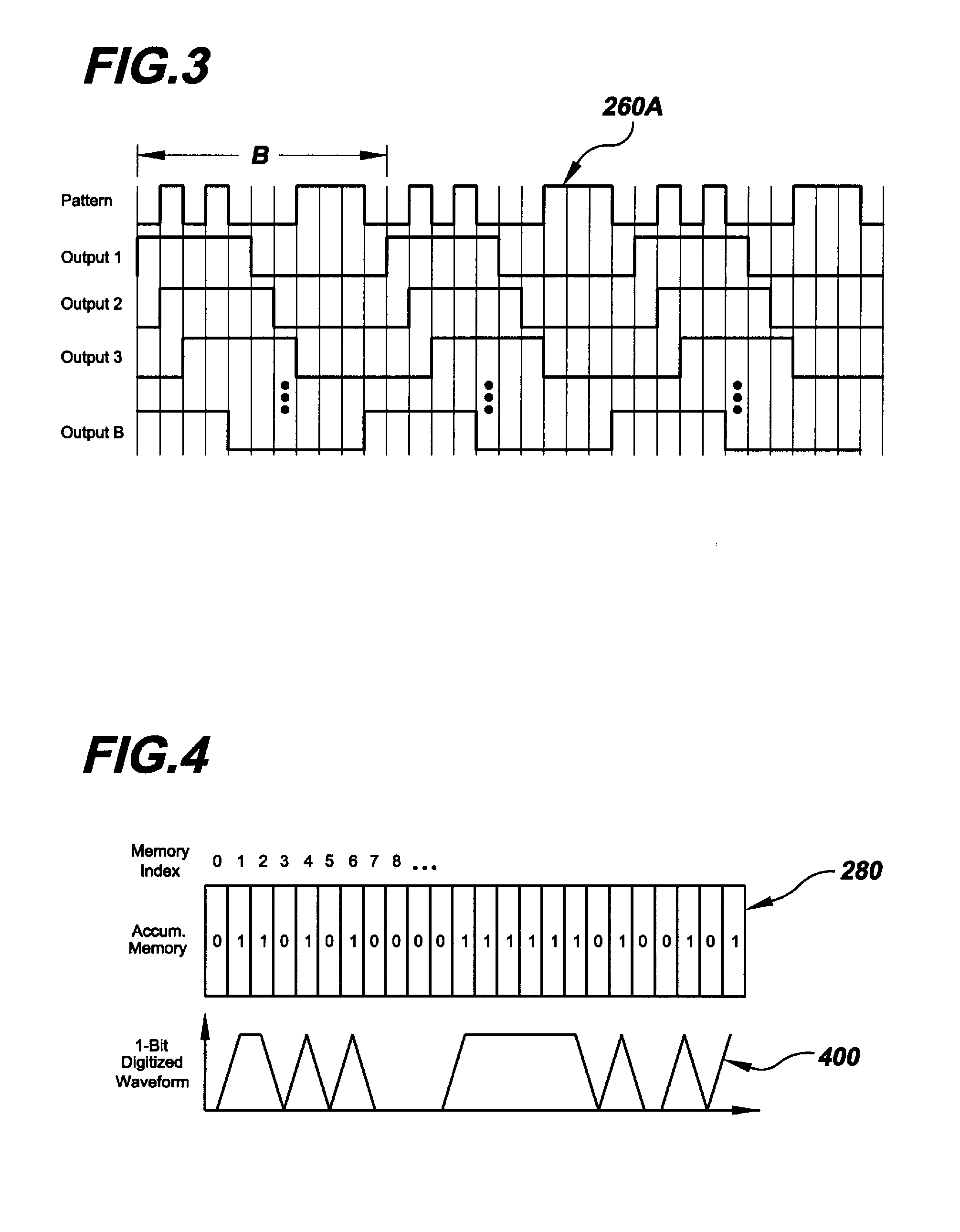
A high-speed signal testing system that includes a digital circuitry for providing a pattern tester with oscilloscope functionality at minimal implementation cost. The digital circuitry includes a time-base generator that provides a high-speed repeating time-base signal. The time-base signal, in conjunction with a sub-sampler and an accumulation memory, allows the system to zoom in on, and analyze portions of, one or more bits of interest in a repeating pattern present on the signal under test. Such portions of interest include rising and falling edges and constant high and low bit values.

Description

RELATED APPLICATION DATA[0001]This application claims the benefit of priority of U.S. Provisional Patent Application Ser. No. 60 / 830,797, filed on Jul. 14, 2006, and titled “Signal Integrity Measurement System And Method Using A Predominantly Digital Time-Base Generator,” which is incorporated herein by reference in its entirety.FIELD OF INVENTION[0002]The present invention relates generally to the measurement of high-speed digital data. More particularly, the present invention is directed to a high-speed signal testing system having oscilloscope functionality.BACKGROUND[0003]Digital communication speeds within semiconductor components, between semiconductor components, and between boards and cabinets continue to increase. As speeds increase, testing digital signals does not only involve logic (pattern) testing, but also requires analog parametric testing. With increased speeds, the analog shape of the voltage waveform representing the binary digital data is important. Poor analog p...

Claims


Application Information

Patent Timeline
IPC IPC(8): H04L12/28
CPCG01R13/02G01R31/31932G01R31/3193
Inventor HAFED, MOHAMED M.
Owner DFT MICROSYST
Learn More