

Steel plate sprocket and method of producing same
- Summary
- Abstract
- Description
- Claims
- Application Information
AI Technical Summary
Benefits of technology
Problems solved by technology
Method used
Image

Examples
Embodiment Construction
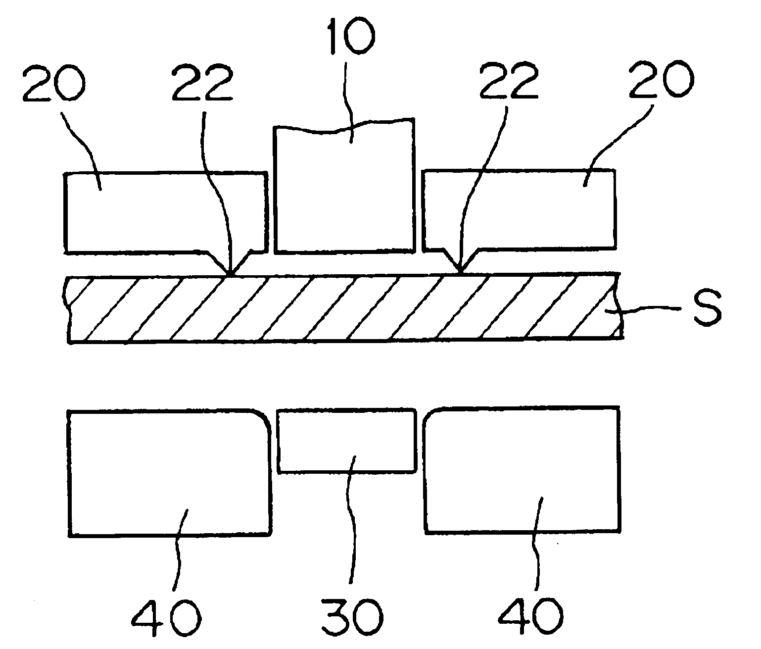
[0024]FIGS. 1(a) to 1(f) illustrate the progress of the fine blanking operation, which is the first step of the process according to the invention. The figures show the fine blanking of a steel plate sprocket.
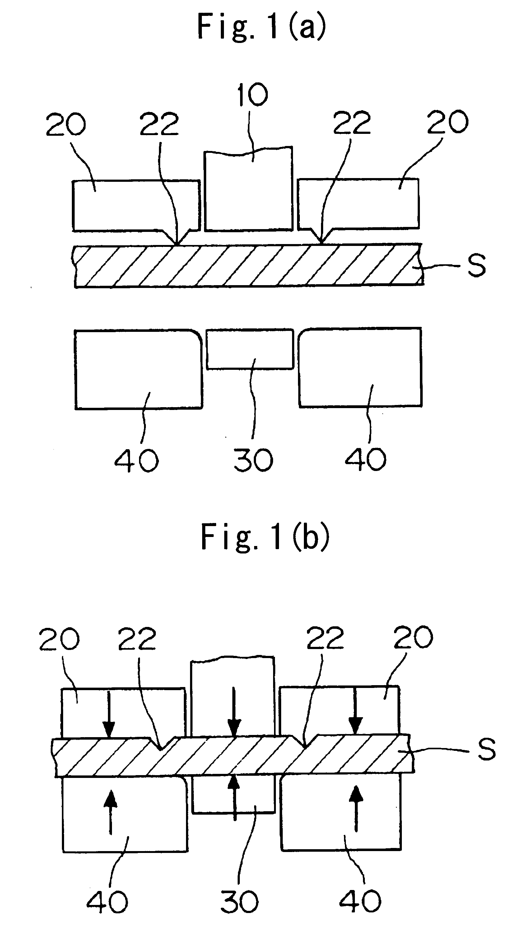
[0025]As shown in FIG. 1(a), a steel plate S is passed through a metal mold for fine blanking. The metal mold comprises a punch 10 and a cooperating die 40, a back-up plate 20, opposed to the die 40 and having a knife edge-shaped V-ring 22, and a reverse punch backup 30 opposed to the punch 10.
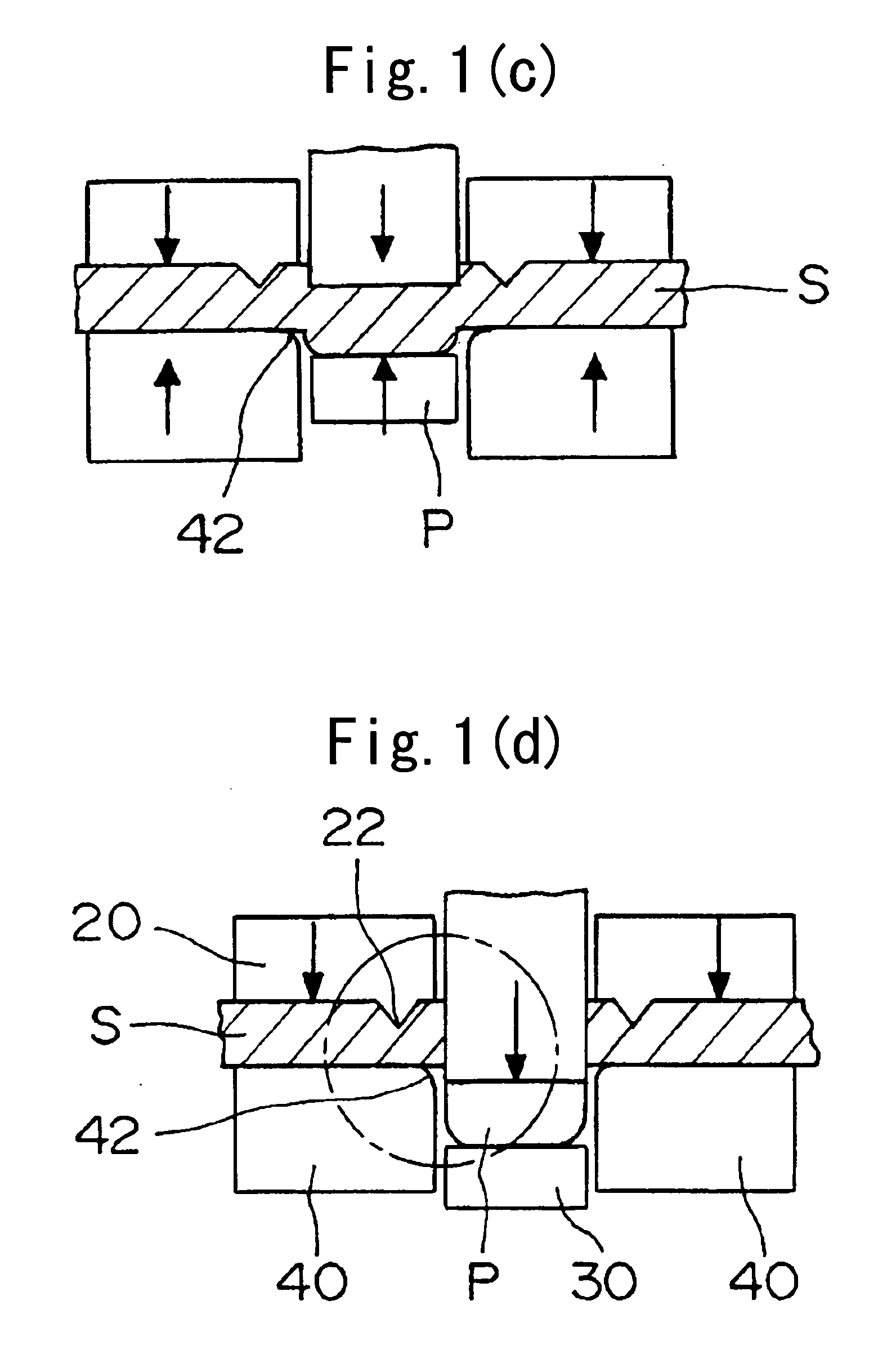
[0026]As shown in FIG. 1(b), a lower mold part, comprising the reverse punch backup 30 and the die 40, is raised, and a pressing force is applied to the plate S. At this time, pressure is applied to the reverse punch backup 30 and the plate backup 20 by means of a hydraulic press (not shown). The knife edge-shaped V ring 22, which is provided on the plate backup 20 along the profile of the product, is pressed into the steel plate S. The steel plate S, which tends to expand in a direction ...
PUM
| Property | Measurement | Unit |
|---|---|---|
| Shape | aaaaa | aaaaa |
Abstract
Description
Claims
Application Information