Automatic control system for feeding through pneumatic conveying

An automatic control system and pneumatic conveying technology, applied in animal feeding devices, applications, animal husbandry, etc., can solve the problems of affecting feed efficacy, pellet feed is easy to be crushed, etc., to avoid biological safety problems, low crushing rate, The effect of long conveying distance

Inactive Publication Date: 2019-12-20
JIANGXI ZENG XIN HUSBANDRY TECH CO LTD
View PDF10 Cites 3 Cited by
  • Summary
  • Abstract
  • Description
  • Claims
  • Application Information

AI Technical Summary

Problems solved by technology

In the past, the feeding supply mode of large-scale pig farms relying on feed transfer vehicles to transport feed can no longer meet the strict biosafety requirements of today, and the traditional large-diamete

Method used


Image

  • Automatic control system for feeding through pneumatic conveying
  • Automatic control system for feeding through pneumatic conveying

Examples


Embodiment 1

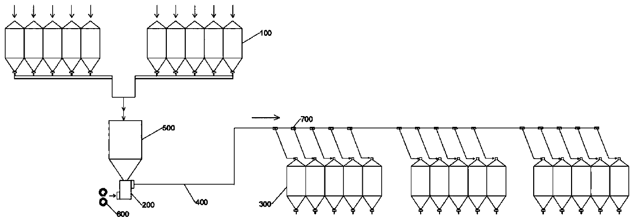
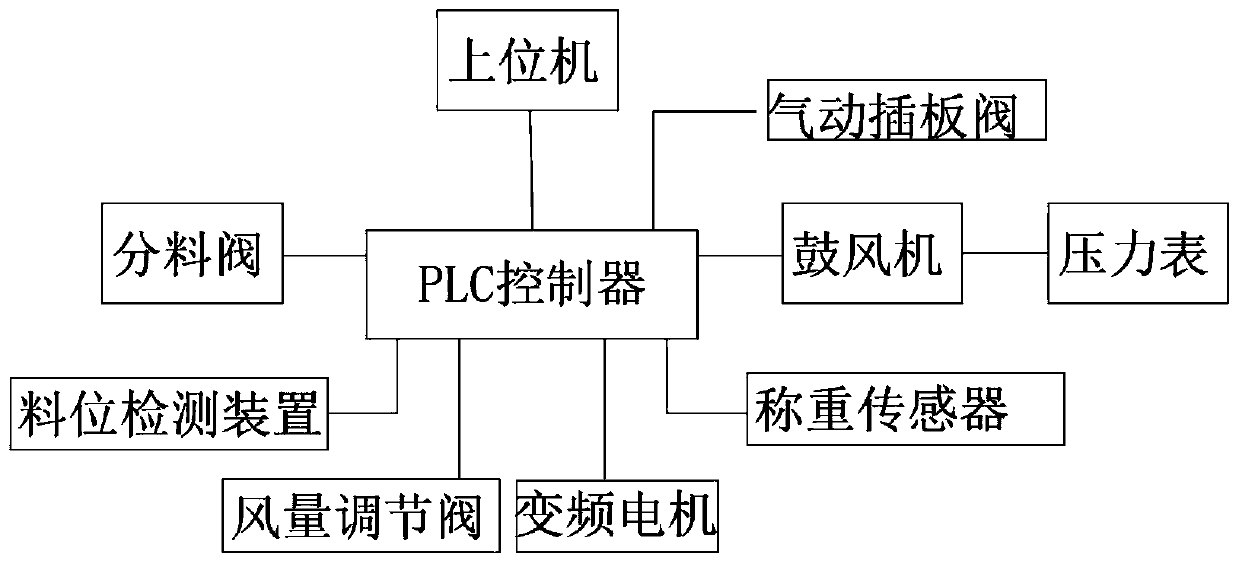
[0029] Such as figure 1 , figure 2 As shown, an automatic control system for feeding materials by means of pneumatic conveying includes a control system and a controlled system, the control system includes a PLC controller, and the PLC controller is electrically connected to a host computer system, and the host computer system It includes an industrial computer, a display and a memory connected to the industrial computer, and the display is used to display the interface of the state of the controlled system;

[0030] The controlled system includes a main material tower 100, an intermediate tower 500, a gas-material mixing chamber 200, and a material distribution tower 300 arranged sequentially along the feeding direction through a conveying pipeline 400;

[0031] The controlled system also includes a blower 600, and the air outlet of the blower 600 communicates with the gas material mixing chamber 200;

[0032] The branch pipe of the delivery pipeline 400 connected to the m...

Embodiment 2

[0037] This embodiment is a further optimization made on the basis of Embodiment 1. Specifically, an unloader is provided at the bottom of the intermediate tower 500, and the unloader is driven by a frequency conversion motor; the bottom of the unloader and the gas material The mixing chamber 200 is connected, and the frequency conversion motor is connected with the PLC controller for electrical signals.

Embodiment 3

[0039] This embodiment is a further optimization made on the basis of Embodiment 2. Specifically, three load cells are arranged on the weighing bucket, and a three-point weighing mode is implemented. The load cells are electrically connected to the PLC controller. signal connection.


PUM


Abstract

The invention discloses an automatic control system for feeding through pneumatic conveying. The automatic control system comprises a control system body and a controlled system; the control system body comprises a PLC, the PLC is in electric signal connection with a host computer system, the host computer system comprises an industrial computer, a displayer and a memory, and the displayer and thememory are connected to the industrial computer; the controlled system comprises main material towers, an intermediate tower, an air-material mixing chamber and branch material towers, and the main material towers, the intermediate tower, the air-material mixing chamber and the branch material towers are sequentially arranged in the feeding direction through a conveying pipeline; the controlled system further comprises an air blower, and an air outlet of the air blower is communicated with the air-material mixing chamber; branch pipes, communicated with the branch material towers, of the conveying pipeline are provided with branching valves, and the branching valves are in electric signal connection with the PLC. The invention further discloses a control method. Automatic and accurate feeding is achieved; the feeding time is short, the conveying distance is long, and the breakage rate of granular feed is low; the operation is convenient, and the labor cost is reduced; the biological safety problems caused by feed transfer are effectively avoided.

Description

technical field [0001] The invention relates to the field of feeding systems, in particular to an automatic control system for feeding materials in a pneumatic conveying manner. Background technique [0002] It is widely used in the loading and unloading of plastic granules, cement, grain, flour, ore, coal powder, coal ash, molding sand and other bulk materials in the chemical industry, building materials, grain, mining, metallurgy, mechanical power and other departments in my country. With the spread of African swine fever in China, the animal husbandry industry pays more and more attention to the biosecurity of pig farms. In the past, the feeding supply mode of large-scale pig farms relying on feed transfer vehicles to transport feed can no longer meet the strict biosafety requirements of today, and the traditional large-diameter auger feeding mode can not meet the feeding needs of large-scale pig farms, and the traditional In the process of conveying the feed, the pellet...

Claims


Application Information

Patent Timeline
IPC IPC(8): A01K5/02
CPCA01K5/02A01K5/0283
Inventor 张凯徐云波王国军潘自荣
Owner JIANGXI ZENG XIN HUSBANDRY TECH CO LTD
Why Eureka
Try Eureka