Component mounting position correcting method and component mouting apparatus

Inactive Publication Date: 2008-01-17
JUKI CORP
View PDF3 Cites 13 Cited by
  • Summary
  • Abstract
  • Description
  • Claims
  • Application Information

AI Technical Summary

Benefits of technology

[0029] Further, even when there is an assembly of a plurality of circuits, the common result of recognizing the printing misalignment amount of the solder can be shared by the plurality of circuits. Therefore, it is not necessary to recognize the printing misalignment amount of the solder for each of the circuits so that a time for detecting the printing misali

Problems solved by technology

However, the technology disclosed in JP-A-5-267899 relates to a misalignment in a positioning the printed circuit board when the printed circuit board is fixed to the mounting execution portion of the compone

Method used


Image

  • Component mounting position correcting method and component mouting apparatus
  • Component mounting position correcting method and component mouting apparatus
  • Component mounting position correcting method and component mouting apparatus

Examples


Embodiment Construction

[0036] Hereinafter, exemplary embodiments of the invention will be described in details with reference to the drawings.

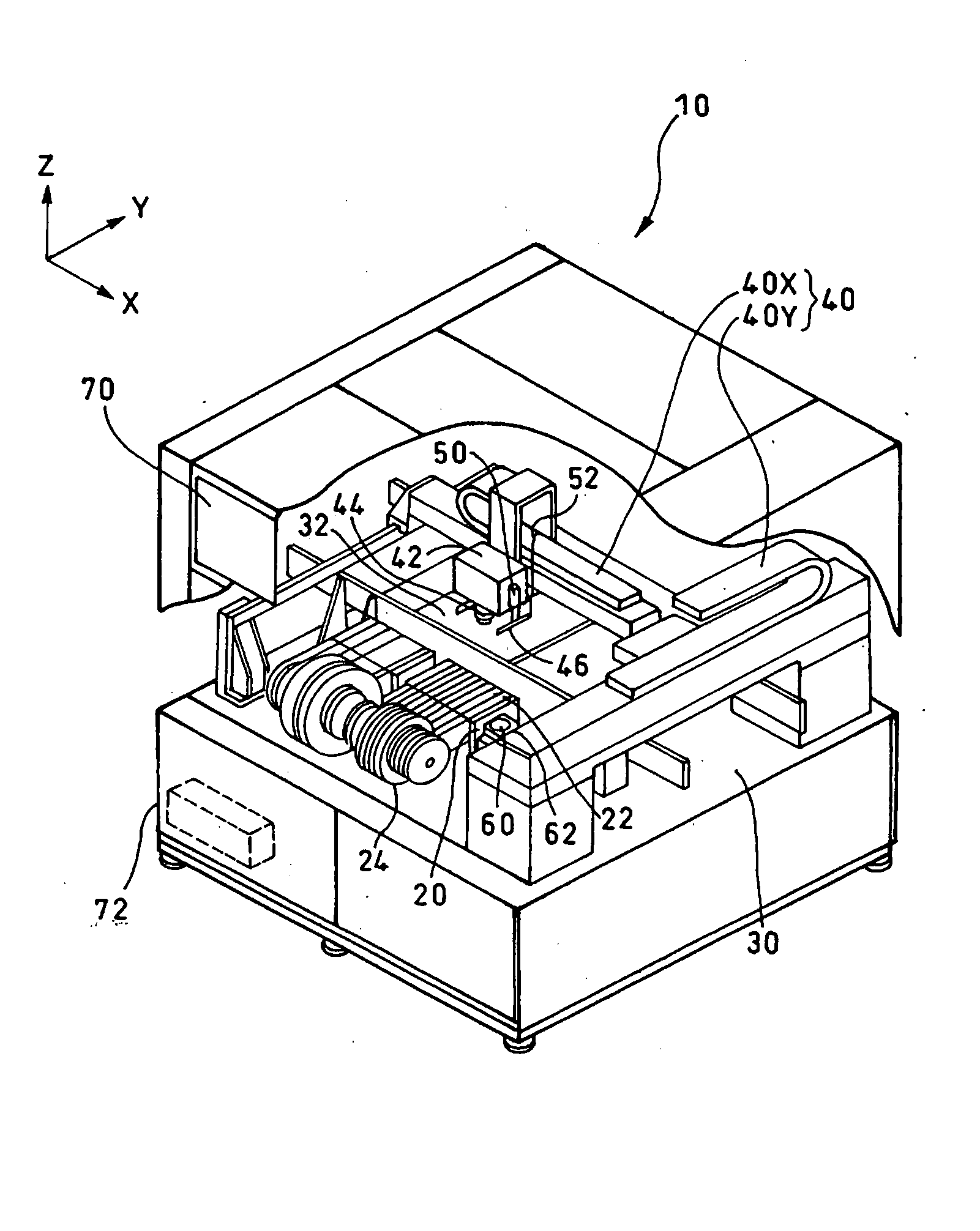
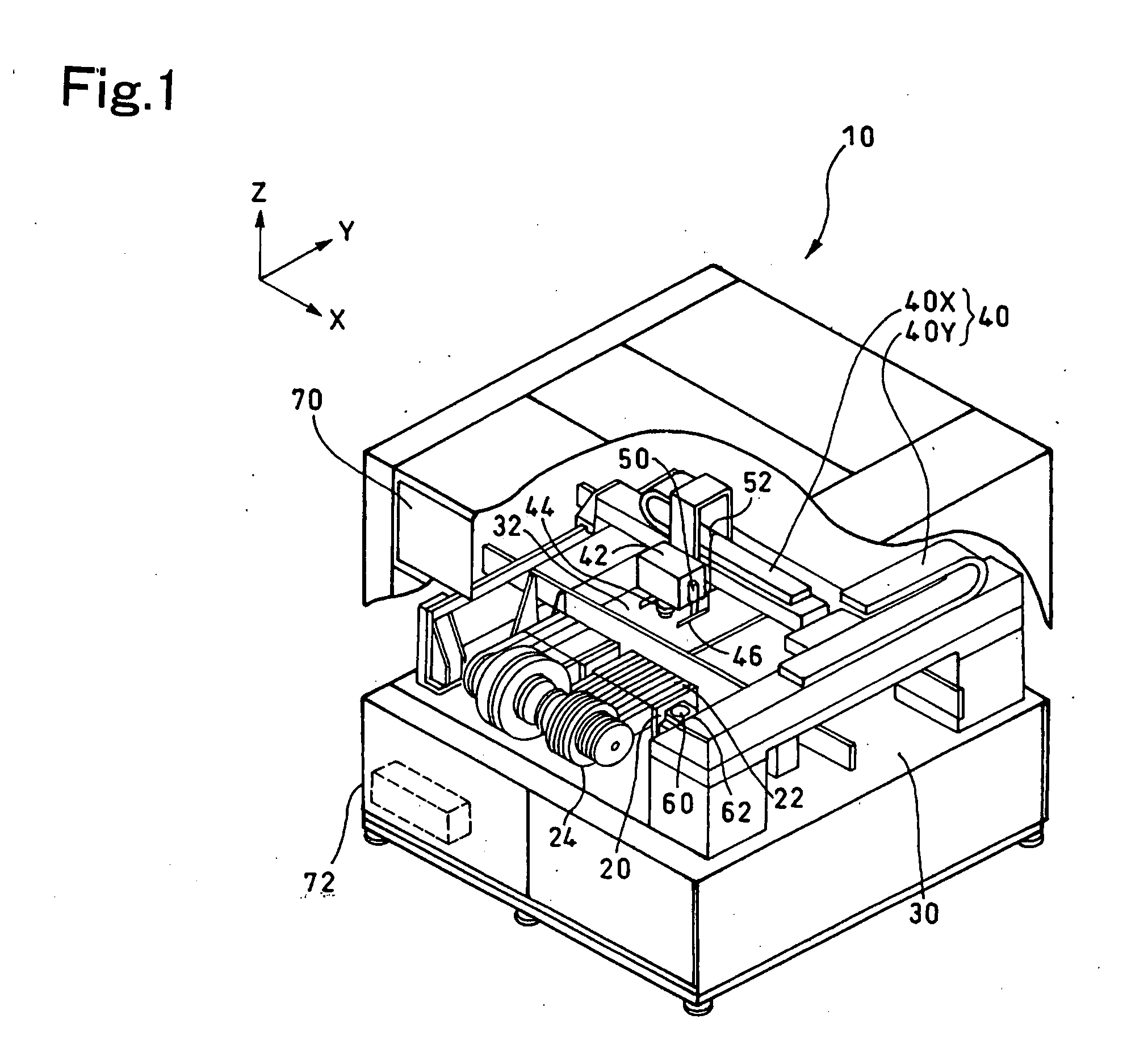
[0037]FIG. 1 shows an outline view of an electronic component mounter. The electronic component mounter 10 includes a component supplying portion 20 arranged at a front portion thereof (a left lower side in the drawing), a board delivering portion 30 extending in a direction from a left upper aide to a right lower side in the drawing slightly on a rear side from its center portion, and an XY transferring portion 40 having an X axis gantry 40X and a Y axis gantry 40Y. The board delivering portion 30 delivers a board 32 on which a component 22 is to be mounted. The XY transferring portion 40 is arranged so as to be movable toward the front portion of the electronic component mounter 10.

[0038] In the component supplying portion 20, a plurality of tape feeders 24, each storing a plurality of the components 22 therein, is arranged in lines.

[0039] A sucking head portio...


PUM


Abstract

A component mounting position is corrected in accordance with a printing misalignment amount of a solder with respect to an original mounting position on a board at which a component is to be mounted. More specifically, a mounting position of a predetermined correction object component is corrected in accordance with the printing misalignment amount of the solder printed on a predetermined detection object electrode.

Description

[0001] The present invention claims priority from Japanese Patent Applications No. 2006-194441 filed on Jul. 14, 2006, No. 2007-081557 filed on Mar. 27, 2007, and No. 2007-174390 filed on Jul. 2, 2007, the entire contents of which are incorporated herein by reference. TECHNICAL FILED [0002] The present invention relates to a component mounting position correcting method and a component mounting apparatus. Specifically, the present invention relates to a component mounting position correcting method which is suitable for mounting an electronic component (also simply referred to as a component) on a board with a component mounting apparatus and is capable of accurately mounting the component on the board by detecting a printing misalignment amount of a solder with respect to a component mounting position and correcting the component mounting position in accordance with the printing misalignment. The present invention also relates to a component mounting apparatus operable to perform s...

Claims


Application Information

Patent Timeline
IPC IPC(8): H05K1/00
CPCH05K1/0269H05K3/303H05K2203/166H05K13/0413H05K13/08H05K3/3484H05K3/3485H05K13/0817H05K13/083Y02P70/50
Inventor OGURA, YUTAKAOHASHI, TAKAHIRO
Owner JUKI CORP
Why Eureka
Try Eureka