Power tool with spindle lock

a technology of power tools and spindles, which is applied in the direction of portable power-driven tools, metal-working equipment, portable grinding machines, etc., can solve the problems of large force required to ultimately “set” the screw, the hand grinder cannot reach many hidden or obstructed work surfaces, and requires excessive work or modification to reach many work surfaces

Inactive Publication Date: 2008-01-17
PONTIERI JAMES MATTHEW
View PDF25 Cites 44 Cited by
  • Summary
  • Abstract
  • Description
  • Claims
  • Application Information

AI Technical Summary

Benefits of technology

[0015]An object of the present invention is to develop a spindle locking mechanism for a hand-held power tool which employs a manually operable lever which displaces a locking pin between a retracted position which frees the spindle drive to rotate a tool, and a locked position which prevents rotation of the associated tool spindle, for repair or replacement of the tool, or the like.

Problems solved by technology

However, previously known hand grinders have not been able to reach many hidden or obstructed work surfaces or have required excessive work or modification to reach many work surfaces.
In particular, very large forces may be required to ultimately “set” the screw during installation or to initially “break loose” the screw during removal.
Difficulties have been encountered in generating these large driving forces, particularly in small hand-held tools where size and weight considerations necessarily limit the available motor horsepower.
In such a tool it has been found that batteries of sufficient electrical capacity to power a high-torque cordless screw-driver tool are impractical due to inherent size and weight limitations.
In manual work, for instance, by attaching various tools by mounting a chuck on the output shaft of a power tool, if the power switch is turned off, the output continues to rotate by inertia of the chuck or tool, and if the power tool is released from the user's hand during this rotation, the tool is still rotating and can pose a risk of injury.
If an attempt is made to tighten the chuck by hand, the output shaft also rotates and it cannot be tightened by hand.
Hence it is necessary to fix the output shaft by one hand, and the controllability is poor because of hand tightening of the chuck and holding of the tool.

Method used


Image

  • Power tool with spindle lock
  • Power tool with spindle lock
  • Power tool with spindle lock

Examples


Embodiment Construction

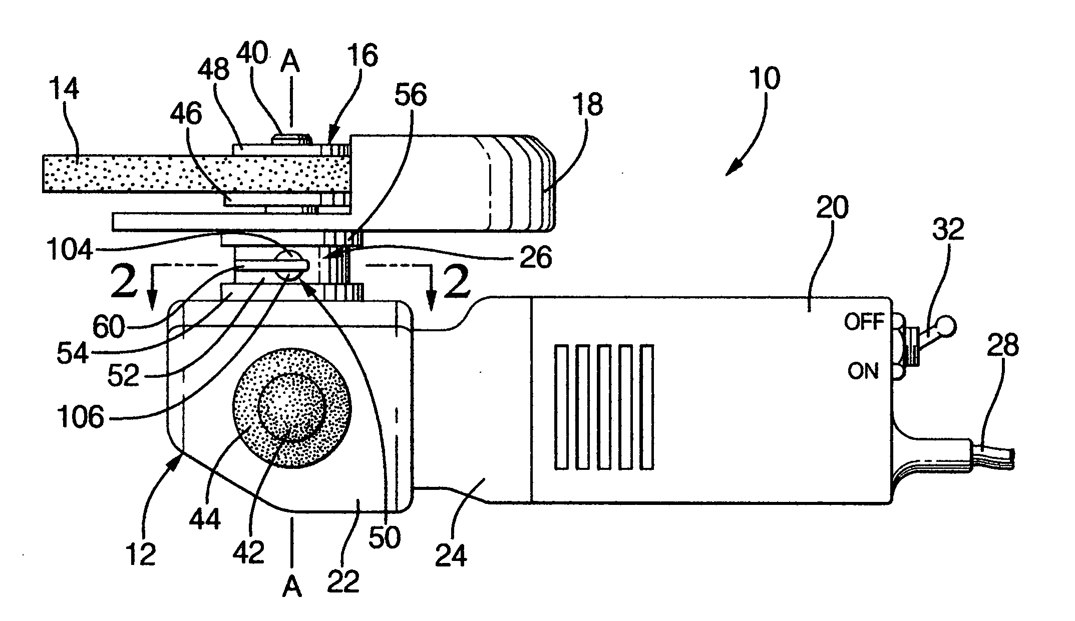
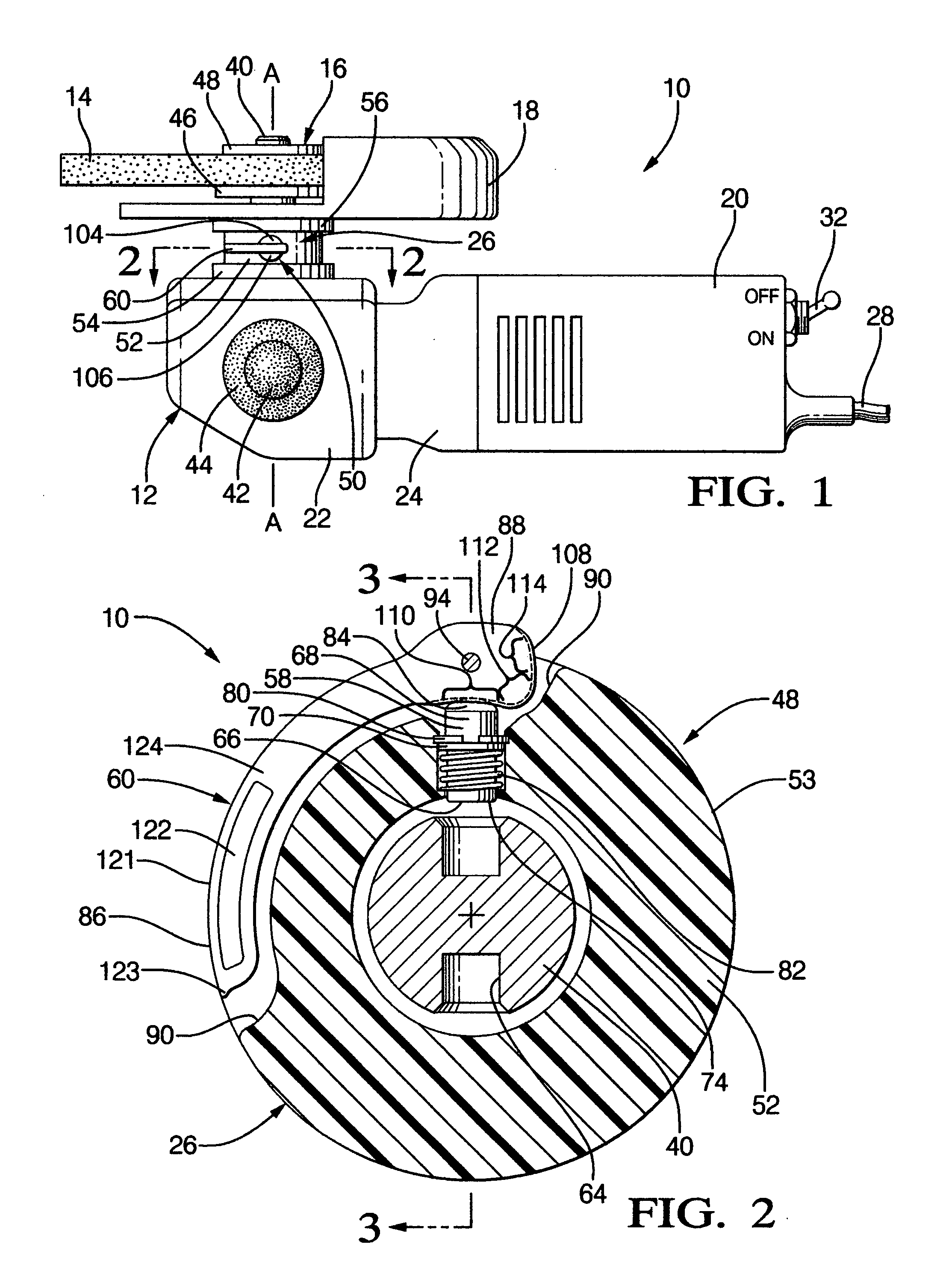
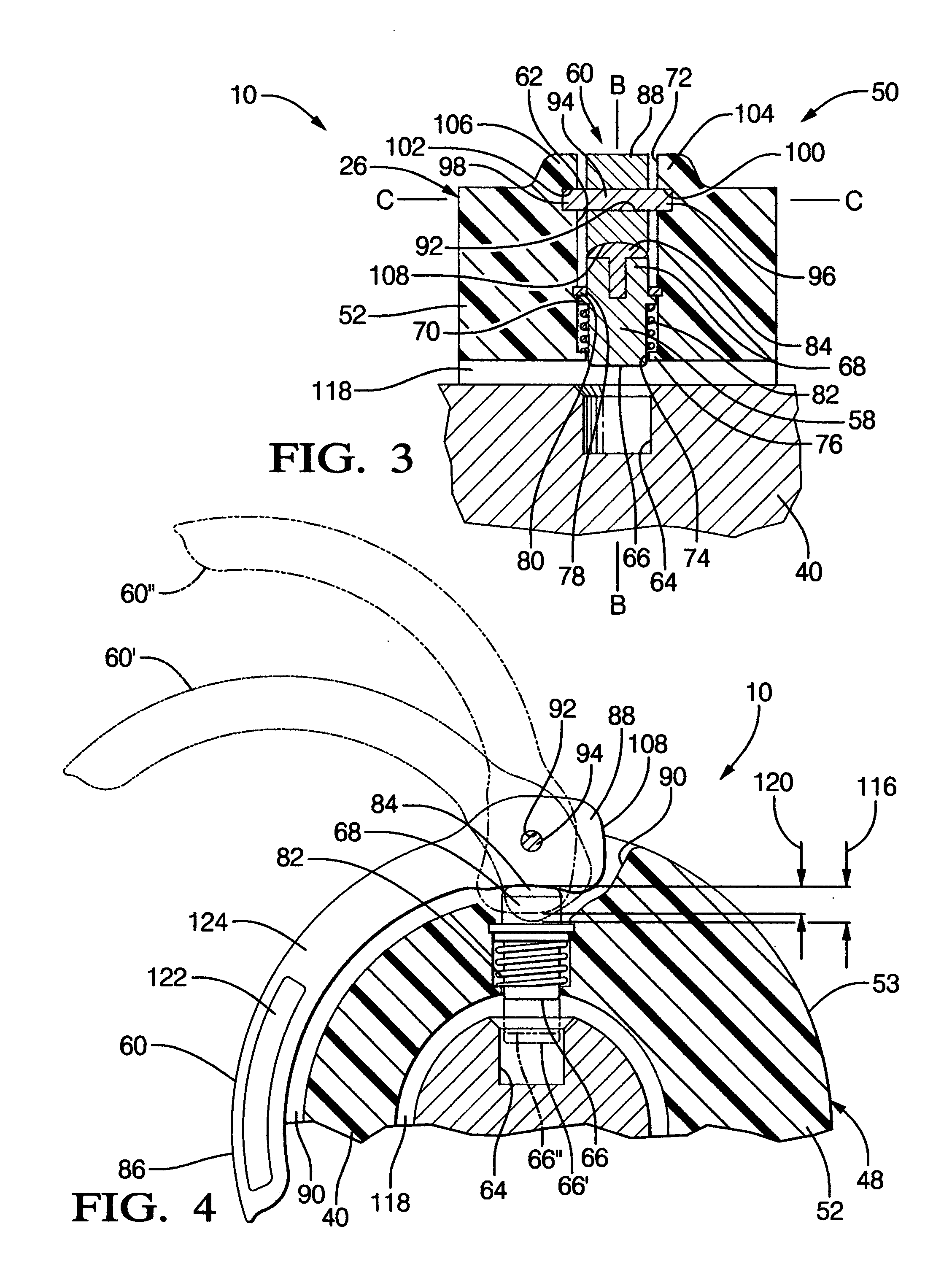
[0025]For purposes of illustration, the present invention is implemented within a specific type of hand-held power tool, in particular, a hand-held industrial grinder. However, it can be applied with equal success with other commercial or light duty hand-held power tool types such as a circular saw, drill, screw driver, or the like. is carried with the housing assembly which is selectively displacable along a fixed axis between a locked position in which a first end portion of the lock member engages a rotating element of the drive train to prevent rotation of the spindle, and a released position in which the first end portion of the lock member is spaced from the rotating element to permit rotation of the spindle. Resilient means, such as a compression spring, continuously urges the lock member toward the released position to provide fail-safe operation. Finally, a lever is carried externally of the housing assembly and engages the lock member. The lever is manually operable to dis...


PUM


Abstract

A spindle lock equipped hand-held power tool, such as a grinder or circular saw, includes a housing assembly, a motor including a rotating armature shaft, a spindle carried externally of the housing adapted for selectively affixing and releasing a rotating cutting tool and a drive train which drivingly interconnects the motor armature shaft and spindle for the application of torque to the tool upon electrical energization of the motor. A lock member carried in the housing is selectively displaceable along a fixed axis between a locked position wherein it engages a rotating element of the drive train to prevent rotation of the spindle, and a released position. A spring continuously urges the lock member toward the released position. A manually operable lever selectively displaces the lock member between the released and locked positions.

Description

RELATED APPLICATION[0001]The present application claims the benefit of U.S. Provisional Application No. U.S. Ser. No. 60 / 831,436, entitled “POWER TOOL SPINDLE LOCK” filed 17 Jul. 2006.TECHNICAL FIELD[0002]The present invention relates generally to hand-held power tools, and, more particularly, to such tools which include a driven spindle configured for drivingly engaging a sacrificial cutting or forming accessory.BACKGROUND OF THE INVENTION[0003]Hand-held grinders are common tools that are used for a variety of applications. Typically, a grinder includes a motor that drives a wheel (such as a grinding wheel, wire brush, or cutting disc). Many grinders include a drive shaft from the motor and a gear system coupled to the drive shaft that changes the direction of rotation. Often, the direction of rotation is changed by 90°. Also, many grinders include a lock pin that can be pressed inwardly to lock the drive shaft relative to the housing of the grinder so that a clamping screw can be ...

Claims


Application Information

Patent Timeline
Patent Type & Authority Applications(United States)
IPC IPC(8): B24B27/08
CPCB25F5/001B24B23/022
Inventor PONTIERI, JAMES MATTHEW
Owner PONTIERI JAMES MATTHEW
Why Eureka
Try Eureka