System for improving both energy efficiency and indoor air quality in buildings

a technology for applied in ventilation systems, lighting and heating apparatuses, heating types, etc., can solve problems such as unhealthy conditions, increased concentration, and difficulty in adjusting ventilation, and achieve the effect of improving indoor air quality and energy efficiency

Inactive Publication Date: 2008-01-17
SPADAFORA PAUL F +2
View PDF5 Cites 79 Cited by
  • Summary
  • Abstract
  • Description
  • Claims
  • Application Information

AI Technical Summary

Benefits of technology

[0016]This invention describes a system whereby a greenhouse is integrated into and is a functional part of a building's HVAC system. The greenhouse serves as a means to recover heat and humidity from the building's heated exhaust air in the winter and a means to recover the cooling from the building's air conditioned exhaust air in the summer. The greenhouse contains selected plants that have the ability to remove CO2 and other airborne pollution from the exhaust air and to emit oxygen and beneficial negatively charged ions into the air. The resultant oxygenated air containing the beneficial negatively charged ions is then used to supply all or a portion of the makeup air to the building's HVAC system. Energy consumption is further minimized and indoor air quality in the building is kept at a high level by using temperature, humidity and CO2 concentration sensors at strategic points in the HVAC system and greenhouse and using a computer controller containing algorithms that use a novel feed forward control strategy. This control strategy uses the rate of change in the slope of the temperature, humidity and CO2 level curves to modulate the control devices. The change in the magnitude of the slope prior to reaching the target levels of temperature, humidity and CO2 is used to predict the equilibrium control points and this information is used for feed forward control rather than waiting for feed back information from set points before taking action. This method prevents overshooting and cycling around the set points while maintaining good indoor air quality. By controlling building air circulation, air exhaust and inlet air makeup rates at the minimum required to maintain the target levels of temperature, humidity and CO2 concentration, energy consumption is kept at the lowest practical level.

Problems solved by technology

However, proper ventilation becomes more difficult as the building gets more airtight.
In winter, when heating is required, reducing the amount of warm, moist exhaust air to the atmosphere and restricting the amount of cold, dry atmospheric makeup air aids energy conservation but leads to the increase in the concentration of CO2 and other pollutants in the circulating air resulting in unhealthy conditions.
In the summer when air conditioning is required, reducing the amount of cold, dry exhaust air to the atmosphere and restricting the amount of hot, moist inlet makeup air from the atmosphere also saves energy but also leads to an increase in the concentration of CO2 and other pollutants in the building circulating air resulting in unhealthy conditions.
These heat exchange systems are relatively expensive to install and maintain, require a great deal of space and only a relatively small amount of heat or cooling is recovered.
The heat exchangers are also subject to fouling, which reduces the heat transfer and require periodic cleaning adding to maintenance costs.
Therefore, the negative ion count in many buildings is often too low for the well being of the occupants.
The unit described in this patent has no relationship to the HVAC system of the building and has the disadvantage in that it can promote mold growth and release mold spores into the room.
This patent also has the disadvantage in that it has to heat up and humidify the cold, dry ambient air in the winter and cool down and dehumidify the hot, moist ambient air in the summer.

Method used


Image

  • System for improving both energy efficiency and indoor air quality in buildings
  • System for improving both energy efficiency and indoor air quality in buildings
  • System for improving both energy efficiency and indoor air quality in buildings

Examples


Embodiment Construction

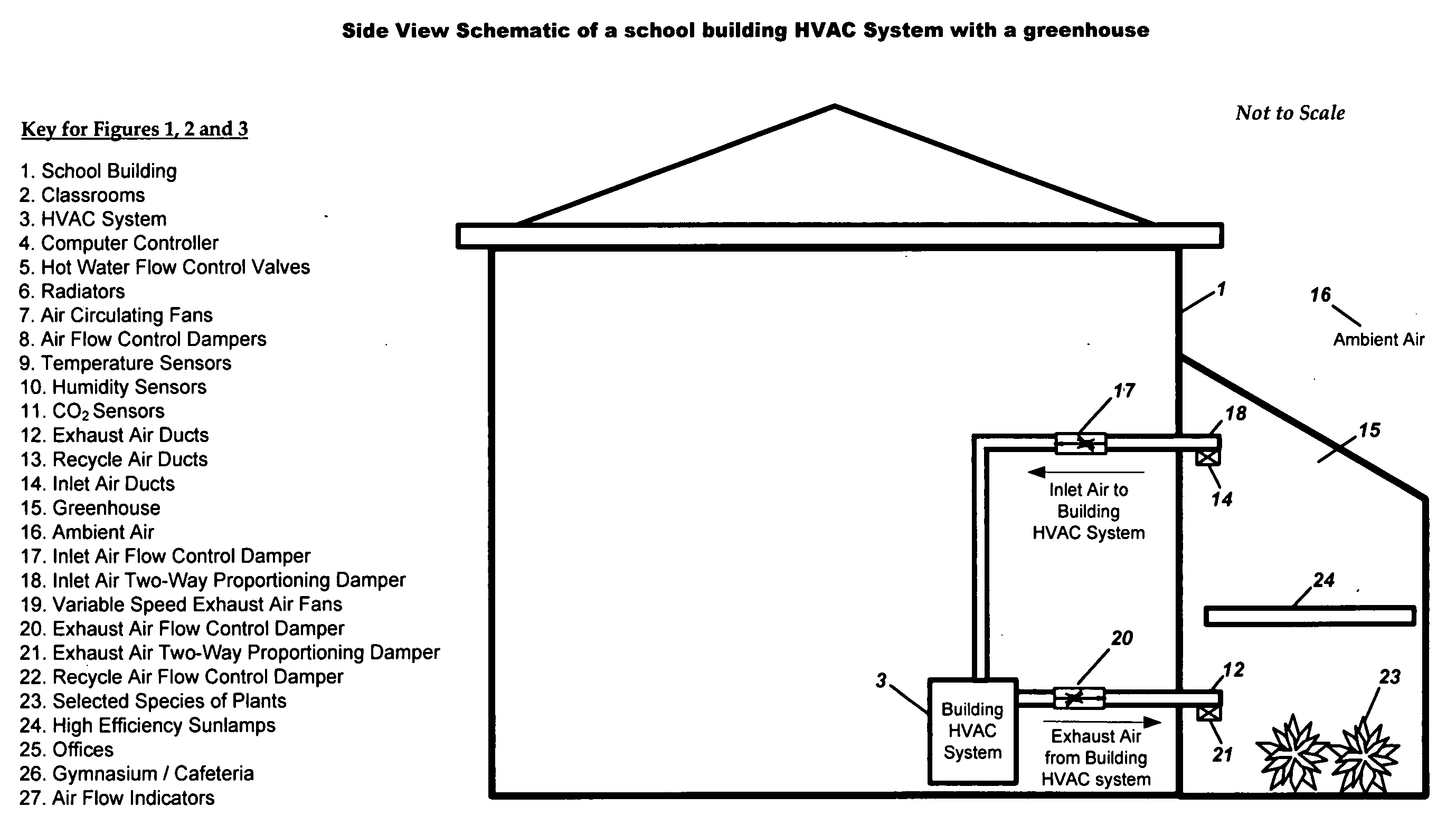
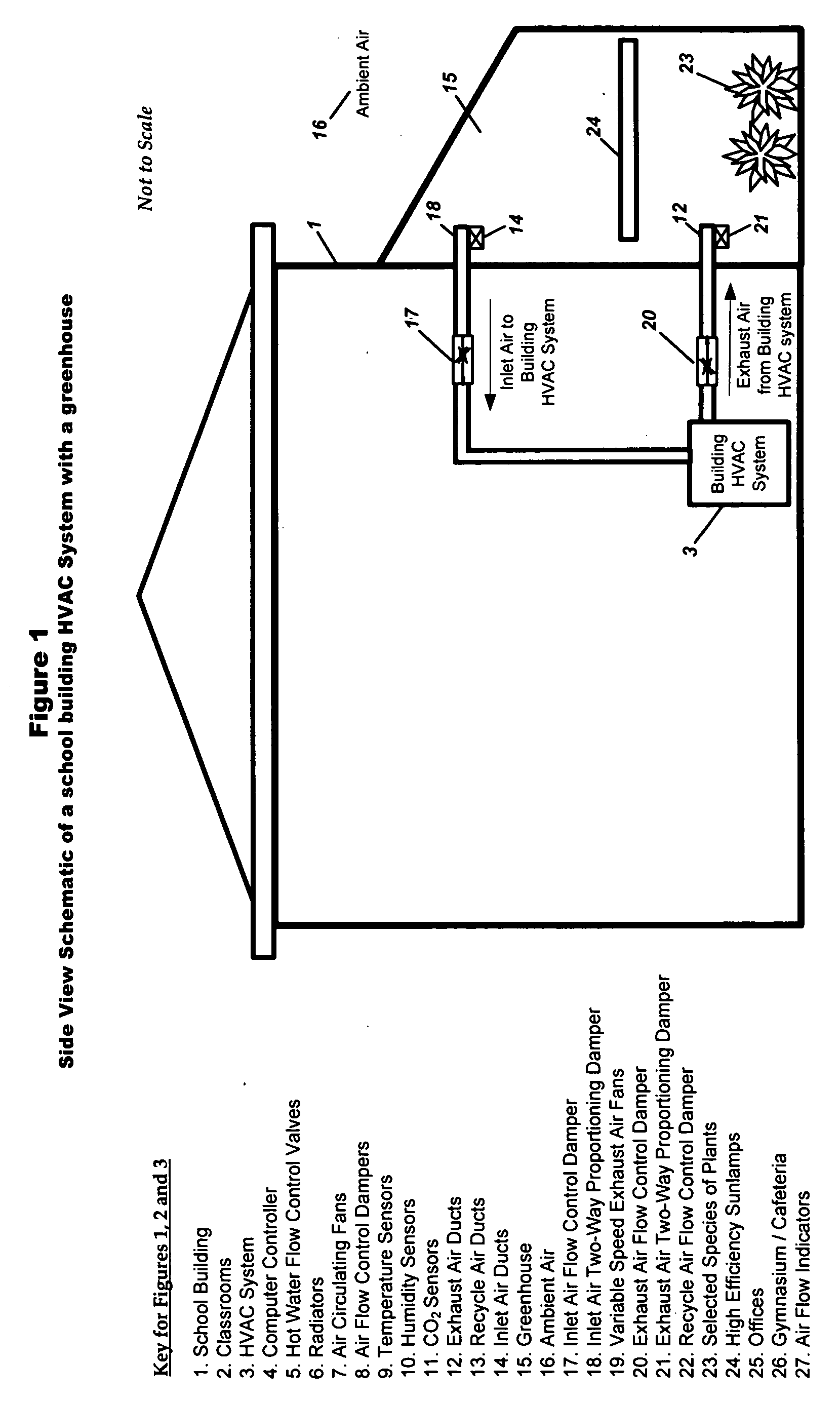
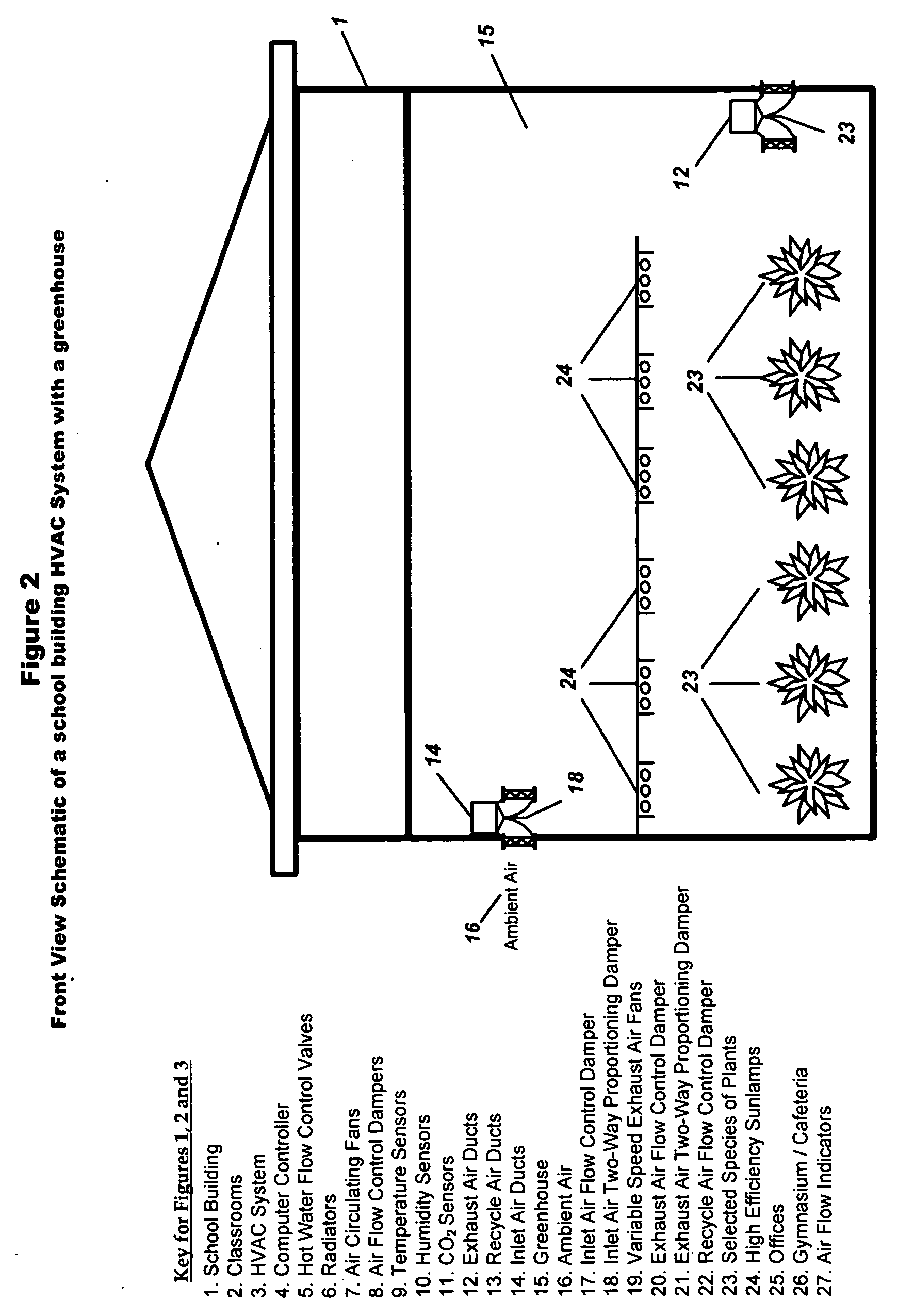
[0026]Using a school building as one example of a type of structure that can be used in the preferred embodiment of this invention, refer to FIGS. 1, 2, 3, 4a, 4b, 5a, 5b, 6a, 6b. For a school building (1) starting on Monday morning during the heating season, the empty classrooms (2) would be at a lower temperature and humidity with minimum circulating air flow. The building air circulation rate, the exhaust air rate and the inlet air rate of the HVAC system (3) would be minimal with low energy consumption. At a preset time before school starts, the computer controller (4) signals the HVAC system (3) to adjust the hot water flow control valve (5) to increase the flow of hot water to the radiators (6) to raise the temperature in the classrooms (2). At the control hot water flow rate, the temperature in the classrooms (2) is below the target value. As teachers and students arrive and the room is being occupied the temperature, humidity and CO2 in the classroom (2) will increase due to...


PUM


Abstract

A building's Heating Ventilating and Air Conditioning (HVAC) system is made more energy efficient and the indoor air quality (IAQ) of the building's circulating air is improved by incorporating a greenhouse as an integral part of the HVAC system and by utilizing a novel feed forward control strategy that maintains the proper levels of temperature, humidity and CO2 concentration in the building under varying conditions of day, time, use and occupancy.A portion or all of the exhaust air from the building is discharged into a greenhouse where the heat and humidity are recovered in the winter by heating the greenhouse and the air conditioning is recovered in the summer by cooling the greenhouse. Selected plants are used in the greenhouse to remove CO2 and pollutants from the building's exhaust air while enriching the air with oxygen and beneficial negatively charged ions. The oxygenated, improved quality air from the greenhouse is then used to supply all or a portion of the intake air to the building's HVAC system.

Description

US PATENT DOCUMENTS[0001]5005787Apr. 9, 1991Cullingford5433923Jul. 18, 1995Wolverton5853460Dec. 29, 1998Alcordo6415617Jul. 9, 2002Seem6727091Apr. 27, 2004DarlingtonOTHER REFERENCES [0002]Final Report NASA / Alca “Interior Landscape Plants for Indoor Air Pollution Abatement” Wolverton Et al. 1989[0003]Biofiltration of Air Pollution Control, J. S. Devinny et al. 1999[0004]Biofiltration of Indoor Air. Llewellyn et, al. date unknown[0005]Development of Biofiltration system of ammonia and VOC. J. R. Kastner March 2003FIELD OF INVENTION[0006]The present invention relates to HVAC systems and Indoor Air Quality (IAQ) in structures and buildings and more particularly it pertains to a system and method whereby a greenhouse and a unique control system is integrated into the HVAC system to improve energy conservation, reduce CO2 and pollutants and increase oxygen and beneficial negative ions in the circulating air of the building or structure.BACKGROUND OF THE INVENTION[0007]Because of the rising...

Claims


Application Information

Patent Timeline
Patent Type & Authority Applications(United States)
IPC IPC(8): F24F11/02F24F8/175
CPCF24F3/16F24F11/0017F24F11/0079Y02B30/78F24F2011/0026Y02B30/746F24F2003/1653F24F11/30F24F2110/50F24F2110/70F24F11/77Y02B30/70F24F8/175F24F11/46F24F11/63
Inventor SPADAFORA, PAUL F.SPADAFORA, RONALD M.SPADAFORA, FRANK E.
Owner SPADAFORA PAUL F
Why Eureka
Try Eureka