
Method and apparatus for microstructure assembly

Inactive Publication Date: 2008-01-24
IND TECH RES INST
View PDF4 Cites 3 Cited by
  • Summary
  • Abstract
  • Description
  • Claims
  • Application Information

AI Technical Summary

Benefits of technology

[0009]It is the primary object of the present invention to provide a method and apparatus for microstructure assembly, capable of accurately aligning microstructures to their corresponding positions by a process of placing the microstructures on droplets formed on pedestals and then removing the droplets.
[0010]It is another object of the invention to provide a method and apparatus for microstructure assembly, capable of being implemented by an automated packaging process integrating automated transportation devices and all sorts of packaging devices, by which a great amount of microstructures can be rapidly aligned and thus the manufacturing cost can be reduced.
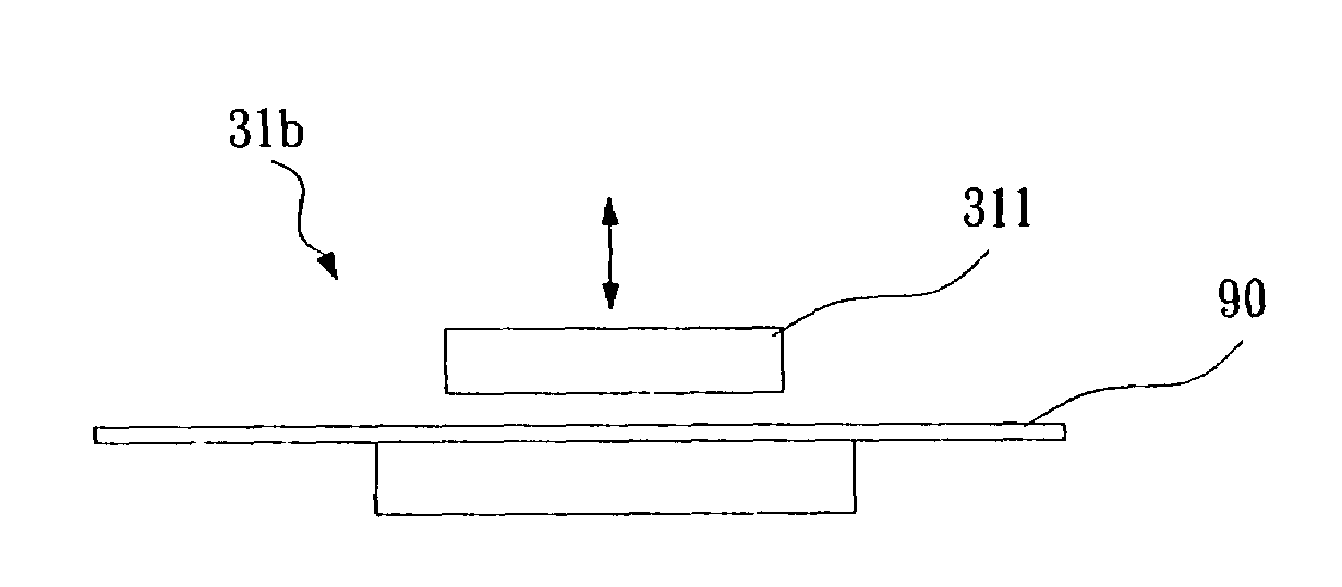
[0028]To achieve the above objects, the present invention provides an apparatus for microstructure assembly, which comprises: a transportation device, for transporting a carrier having a plurality of joints formed thereon; a transfer imprinting device, for receiving the carrier while forming a layer of a paste on each joint; a droplet formation device, for receiving the carrier coated with the paste while forming a droplet on the layer of paste corresponding to each joint; a chip placing device, for providing a plurality of microstructures while placing each microstructure on a droplet corresponding thereto; a droplet removal device, for receiving the carrier carrying the plural microstructures while removing each droplet for jointing each microstructure with its corresponding joint; and a jointing device, capable of providing energy for jointing each microstructure with its corresponding layer of paste.

Problems solved by technology

Conventionally, in the manufacturing cost of such products, the cost of assembly is accounted for more than 20% of the overall manufacturing cost.
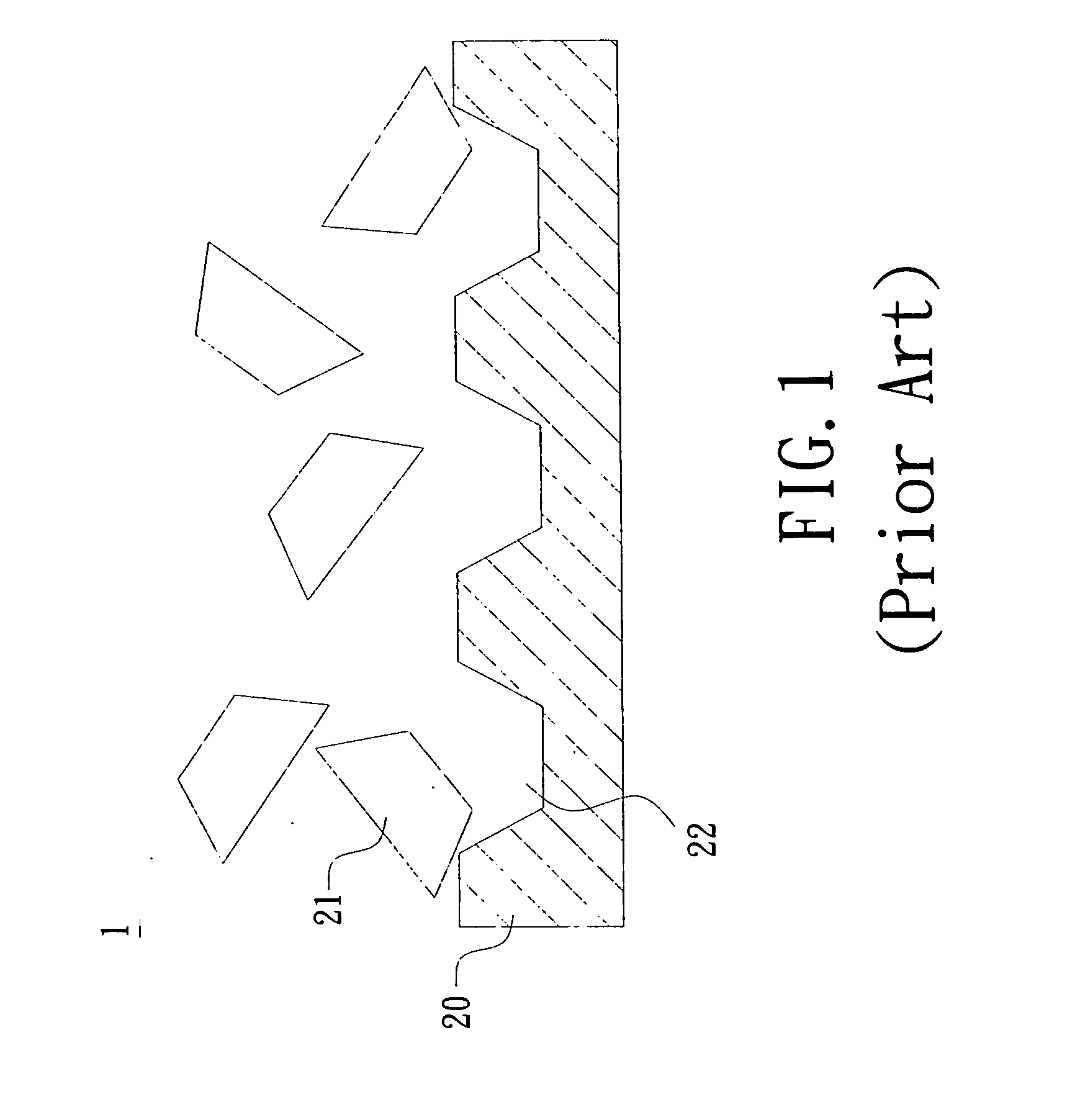
(2) the apparatus of FSA process is huge since it required many -facilities, such as recycling and recovering device, solution control device and drying device, etc.
(3) since the microstructures are required to be soaked in the solution for a certain period of time, they might be damaged by the soaking.
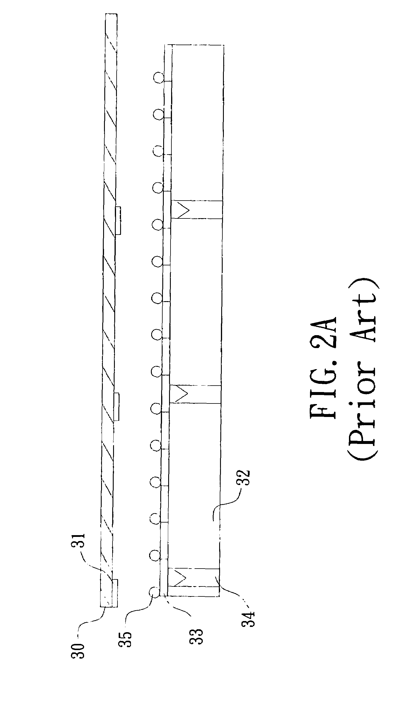
However, the pick-and-place method has shortcomings as following: (1) a complete set of devices, including position sensors, signal processors and position adjusting devices, etc., are required so that the apparatus of the pick-and-place method can be very complicated.
(2) by the pick-and-place method, the aligning and orientating requires a comparatively longer time to achieve.
(3) the smaller the microstructure is, the more costly the aligning by the pick-and-place method will be, since the precision tuning of the robotic arm is hard to achieve.
(4) as the robotic arm can only align one microstructure at one operation, the yield per unit time is low.
However, the aforesaid method of assembling by thimbles still has shortcomings as following: (1) it is costly since it requires very high accuracy.
(2) the conveyer belt is easy to deform, and as more than one thimble are used for rising more than one microstructures for performing multiple jointing at a same time, the accuracy of alignment is hard to achieve.

Method used


Image

  • Method and apparatus for microstructure assembly
  • Method and apparatus for microstructure assembly
  • Method and apparatus for microstructure assembly

Examples


Embodiment Construction

[0052]For your esteemed members of reviewing committee to further understand and recognize the fulfilled functions and structural characteristics of the invention, several preferable embodiments cooperating with detailed description are presented as the follows.

[0053]Please refer to FIG. 3, which is a flow chart depicting a method for microstructure assembly according to a first preferred embodiment of the invention. The flow 4 starts at step 40. At step 40, a carrier 40 is provided, which has a plurality of joint formed thereon to be used for forming electrical connections with microstructures, and then the flow proceeds to step 41. In a preferred aspect, the carrier 40 can be a roll-to-roll carrier, or a flexible substrate or printed circuit board, previously cut into a specific size, and each microstructure can be a RFID chip, a LED chip or other passive components. At step 41, a pedestal is formed on each joint, whereas the pedestal can be made of a hydrophobic material or a hyd...


PUM

PropertyMeasurementUnit
Pressureaaaaaaaaaa
Microstructureaaaaaaaaaa

Abstract

A method for microstructure assembly is disclosed, which comprises steps of: providing a carrier having a plurality of joint formed thereon; forming a pedestal on each joint; forming a droplet on each pedestal; placing a microstructure on each droplet; removing each droplet for enabling the corresponding microstructure to couple with the joint corresponding thereto. In the aforesaid method, the use of the plural droplets is to align the plural microstructures in an automatic manner so as to enable each microstructure to couple with its corresponding joint smoothly. In a preferred aspect, an apparatus for microstructure assembly can be provided with respect to the aforesaid method, which is capable of automating the process of microstructure alignment and assembly.

Description

FIELD OF THE INVENTION[0001]The present invention relates to a component alignment method and the manufacturing apparatus using the same, and more particularly, to a method and apparatus for microstructure assembly capable of rapidly packaging microstructures in high volume by the use of droplets for aligning microstructures and an automated transportation and manufacturing process.BACKGROUND OF THE INVENTION[0002]The miniaturization trend in microelectronics industry continues to drive the development of smaller, higher-efficiency devices, that the radio frequency identification (RFID) tag and the light emitting diode (LED) can be considered as the representative products of such trend since both are formed on a miniature-sized chips and are require in high volume. Conventionally, in the manufacturing cost of such products, the cost of assembly is accounted for more than 20% of the overall manufacturing cost. Therefore, it is worth the relating industry the effort to focus on devel...

Claims


Application Information

Patent Timeline
IPC IPC(8): H05K3/30H01L33/48
CPCB81C3/002B81C2203/058H01L21/67005H01L24/95Y10T29/4913H01L2924/01006H01L2924/01033Y10T29/53174H01L2924/01005H01L2924/12041H01L2924/00
Inventor CHOU, MING-HUNGWENG, WEN-JEY
Owner IND TECH RES INST
Learn More