This helps you quickly interpret patents by identifying the three key elements:
Problems solved by technology
Method used
Benefits of technology
[0016] It is a further object of the present invention to provide a cordless power supply which can supply power to a battery charger for recharging a battery effectively transferring energy from one battery to another.
[0017] It is a further object of the present invention to provide a cordless power supply which can use input po
Problems solved by technology
No known power supply comprises a cordless power supply
Method used
Image
Click on the blue label to locate the original text in one second.
Reading with bidirectional positioning of images and text.
Examples
Example
[0060] The drawings will be better understood when reference is made to the Description of the Invention and Claims which follow hereinbelow.
DESCRIPTION OF THE INVENTION
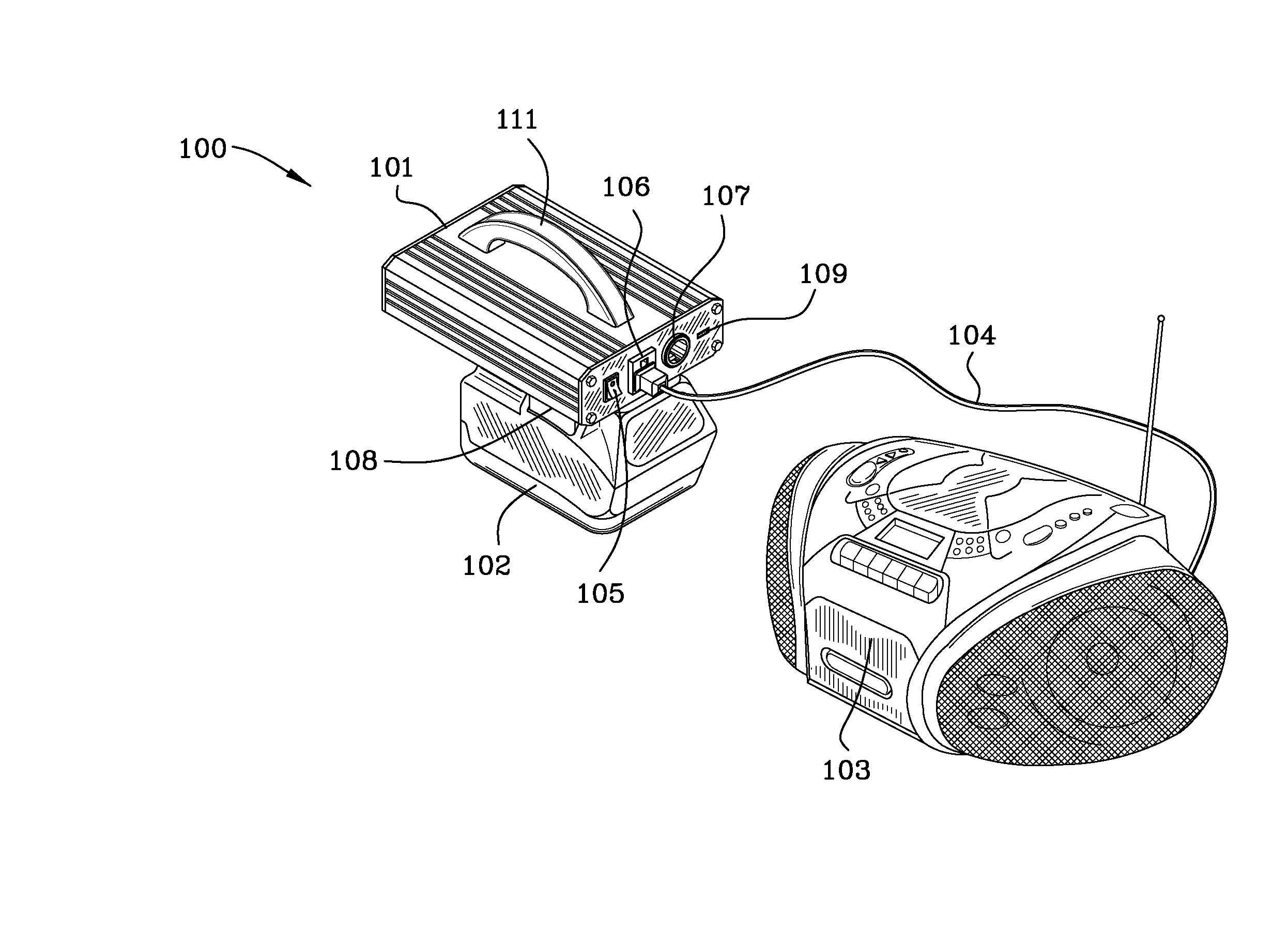
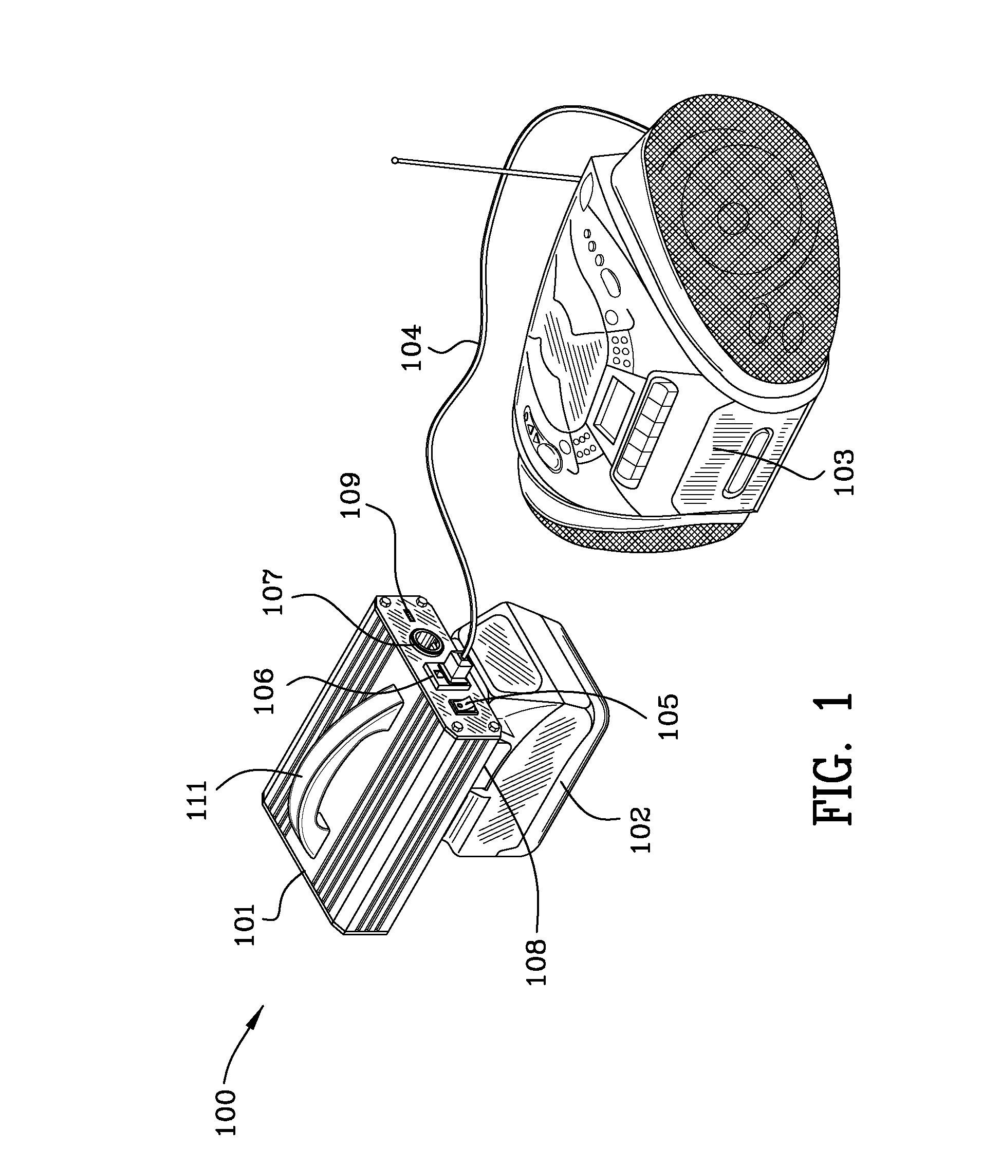
[0061]FIG. 1 is an illustration 100 of a power conversion unit 101 and a cordless tool battery 102 coupled together shown supplying AC power by way of a power cord 104 to a radio / tape player / compact disc player 103. Reference numeral 108 signifies the attachment of the battery 102 to the power conversion unit as is set forth in detail below. Power switch 105 enables power to the alternating current outlet 106, the 12 volt direct current outlet 107 and the 5 volt USB connections 109. Handle 111 facilitates movement of the cordless power supply. The batteries illustrated in FIG. 1, 1A and 1B are high-powered cordless tool batteries manufactured by Milwaukee Electric Tool Corporation of Brookfield, Wis. These higher powered cordless tool batteries are useful in the cordless power supply invention because they operate ...
PUM
Abstract
A cordless power supply comprising a battery, a power conversion unit, a first standard coupling half permanently affixed to the power conversion unit and a second standard coupling half which reciprocally mates with the first standard coupling half is disclosed and claimed. The second standard coupling half includes a first interengaging half and a second interengaging half. The first interengaging half being standardly engageable with the first standard coupling half permanently affixed to the power conversion unit. The second interengaging half is interengageable with a specific battery. The battery may be a dual use cordless tool battery or an original equipment battery. Alternatively, a cordless power supply comprising an interchangeable adapter may be mounted on the power conversion unit for interconnection with a plurality of batteries. Alternatively, a cordless power supply comprising an adapter integral with the power conversion unit may be used with a specific battery type.
Description
RELATED APPLICATIONS, PRIORITY CLAIMS and INCORPORATION BY REFERENCE [0001] Design patent application Ser. No. 29 / 266,852 filed Sep. 29, 2006, Design patent application Ser. No. 29 / 280,875 filed Jun. 8, 2007, U.S. patent application Ser. No. 11 / 672,853 filed Feb. 8, 2007, U.S. patent application Ser. No. 11 / 672,957 filed Feb. 8, 2007, U.S. patent application Ser. No. 11 / 673,551, filed Feb. 9, 2007, U.S. patent application Ser. No. 11 / 851,504, filed Sep. 7, 2007, U.S. Provisional Patent Application Ser. No. 60 / 848,148 filed Sep. 29, 2006, U.S. Provisional Patent Application Ser. No. 60 / 857,079 filed Nov. 6, 2006, U.S. Provisional Patent Application Ser. No. 60 / 855,958 filed Nov. 1, 2006, and U.S. Provisional Patent Application Ser. No. 60 / 911,564 filed Apr. 13, 2007 are related to the instant application. [0002] The instant application claims priority to U.S. Provisional Patent Application Ser. No. 60 / 848,148 filed Sep. 29, 2006 and the entire subject matter set forth therein is inco...
Claims
Application Information
Patent Timeline
Application Date:The date an application was filed.
Publication Date:The date a patent or application was officially published.
First Publication Date:The earliest publication date of a patent with the same application number.
Issue Date:Publication date of the patent grant document.
PCT Entry Date:The Entry date of PCT National Phase.
Estimated Expiry Date:The statutory expiry date of a patent right according to the Patent Law, and it is the longest term of protection that the patent right can achieve without the termination of the patent right due to other reasons(Term extension factor has been taken into account ).
Invalid Date:Actual expiry date is based on effective date or publication date of legal transaction data of invalid patent.