Physical simulations on a graphics processor

a graphics processor and physical simulation technology, applied in the field of graphics processor units, can solve the problems of cpu not possessing parallel processing capabilities, latency and bandwidth problems, etc., and achieve the effect of fast frame rates, and avoiding relatively small time steps

Active Publication Date: 2008-01-24
ATI TECH INC
View PDF9 Cites 52 Cited by
  • Summary
  • Abstract
  • Description
  • Claims
  • Application Information

AI Technical Summary

Benefits of technology

[0007]Embodiments of the present invention, which may include a method, computer program product, and system take advantage of the parallel processing capabilitites available on a GPU to enable faster frame rates as compared to physics simulations executed on a typical CPU. Furthermore, such a method, computer program product, and system utilize an implicit integration technique in the performance of the physics simulations to avoid the relatively small time steps required in explicit integration techniques. Moreover, procedural forces and torques can be represented as a shader program that executes on the GPU(s). In addition, a GPU-based physics simulator can be able to automatically replace a conventional software dynamics solver that typically executes physics simulations on a computer system. Embodiments of the present invention meet the above-identified needs by providing a method, computer program product, and system for performing physical simulations on one or more GPUs. Such a method, computer program product, and system for performing physics simulations on one or more GPUs takes advantage of the parallel processing capabilities available on the GPU(s), thereby enabling faster frame rates compared to physics simulations executed on a typical CPU. Furthermore, such a method, computer program product, and system utilize an implicit integration technique in an embodiment to perform physics simulations, thereby avoiding the relatively small time steps required in explicit integration techniques. Moreover, in accordance with an embodiment of the present invention procedural forces and / or torques are representable as a shader program that executes on the GPU(s). In addition, a GPU-based physics simulator in accordance with an embodiment of the present invention may be used to automatically replace a conventional software dynamics solver that typically executes physics simulations on a computer system.

Problems solved by technology
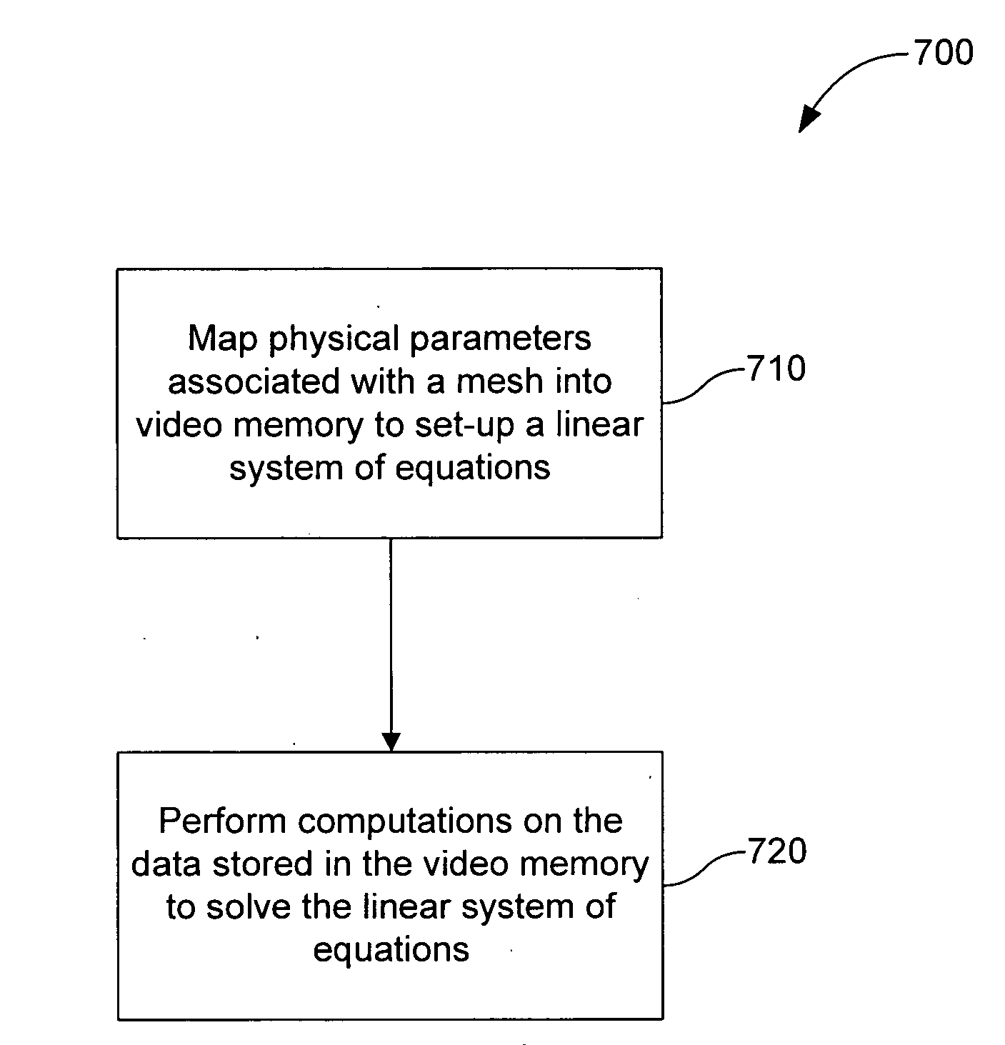
Because the results from the physics engine must be passed to the GPU for rendering, latency and bandwidth problems may arise.
Furthermore, as a general processing unit, a CPU does not possess the parallel processing capabilities of a GPU.

Method used


Image

  • Physical simulations on a graphics processor
  • Physical simulations on a graphics processor
  • Physical simulations on a graphics processor

Examples


example simulation

[0076 tags are shown in Table 2 and example field tags are shown in Table 3.

TABLE 2Simulation TagstagtypeoptionscommentsTypestringCollisioncollision detectionresponsedeterminationcollision detectionand responseTimeStepfloatdecimalsimulation stepperiod (seconds)Fieldsdefined in field tagstable

TABLE 3Field TagstagtypeoptionscommentsDragfloatvector(3)A drag forceDirectionalfloatvector(3)a constant,directional forceProceduralstringanya procedural forcedescription

[0077]The third section of FYSL is actors. A group of actors is typically constructed in a logical grid that can be of one, two or three dimensions. The grid serves as means for deploying actors properties in GPU video memory. Grid tags include width, height and depth values as shown in Table 4.

TABLE 4Grid TagstagTypeoptionscommentsWidthIntegernumericGrid widthHeightIntegernumericGrid heightDepthIntegernumericGrid depth

[0078]An actor is specified by global and specific shape and dynamics properties. Shapes are used to determine ...


PUM


Abstract

The present invention is directed to a method, computer program product, and system for performing physics simulations on at least one graphics processor unit (GPU). The method includes the following steps. First, data representing physical attributes associated with at least one mesh are mapped into a plurality of memory arrays to set up of a linear system of equations that governs motion of the at least one mesh depicted in a scene. Then, computations are performed on the data in the plurality of memory arrays using at least one pixel processor to solve the linear system of equations for an instant of time, wherein modified data representing the solution to the linear system of equations for the instant of time are stored in the plurality of memory arrays.

Description

BACKGROUND OF THE INVENTION[0001]1. Field of the Invention[0002]The present invention is generally directed to graphics processor units, and more particularly to using graphics processor units to perform game physics simulations.[0003]2. Background Art[0004]An application, such as a video game, running on a computer system may require both physics simulations and graphics rendering. For example, FIG. 1 depicts a block diagram 100 of a typical pipeline for computing and displaying the motion of one or more characters depicted in a scene of a video game. In a step 110, physics simulations are performed to determine the motion of the one or more characters depicted in the scene. Then in a step 120, the results of the physics simulations are graphically rendered for visualization by an end-user.[0005]The physics simulations of step 110 are typically performed by a physics engine that is executed on a central processing unit (CPU) or a dedicated device of the computer system. Then, the g...

Claims


Application Information

Patent Timeline
Patent Type & Authority Applications(United States)
IPC IPC(8): G06F17/10G06T13/20G06T15/00
CPCA63F13/00A63F2300/203G06F17/5009A63F2300/643A63F2300/64G06F30/20
Inventor BLEIWEISS, AVI I.BARON, GERARD S.
Owner ATI TECH INC
Why Eureka
Try Eureka