Balanced partial two-stroke engine

a two-stroke engine and partial exhaust gas technology, applied in the direction of machines/engines, mechanical equipment, non-fuel substance addition to fuel, etc., can solve the problems of high cost of ammonia on board production, hazardous storage of ammonia, and inability to meet the requirements of a single-stage, high-efficiency engine, etc., to achieve the effect of facilitating a reaction

a two-stroke engine and partial exhaust gas technology, applied in the direction of machines/engines, mechanical equipment, non-fuel substance addition to fuel, etc., can solve the problems of high cost of ammonia on board production, hazardous storage of ammonia, and inability to meet the requirements of a single-stage, high-efficiency engine, etc., to achieve the effect of facilitating a reaction

US20080022666A1Inactive Publication Date: 2008-01-31CATERPILLAR INC

Image

  • Balanced partial two-stroke engine
  • Balanced partial two-stroke engine
  • Balanced partial two-stroke engine

Examples


Embodiment Construction

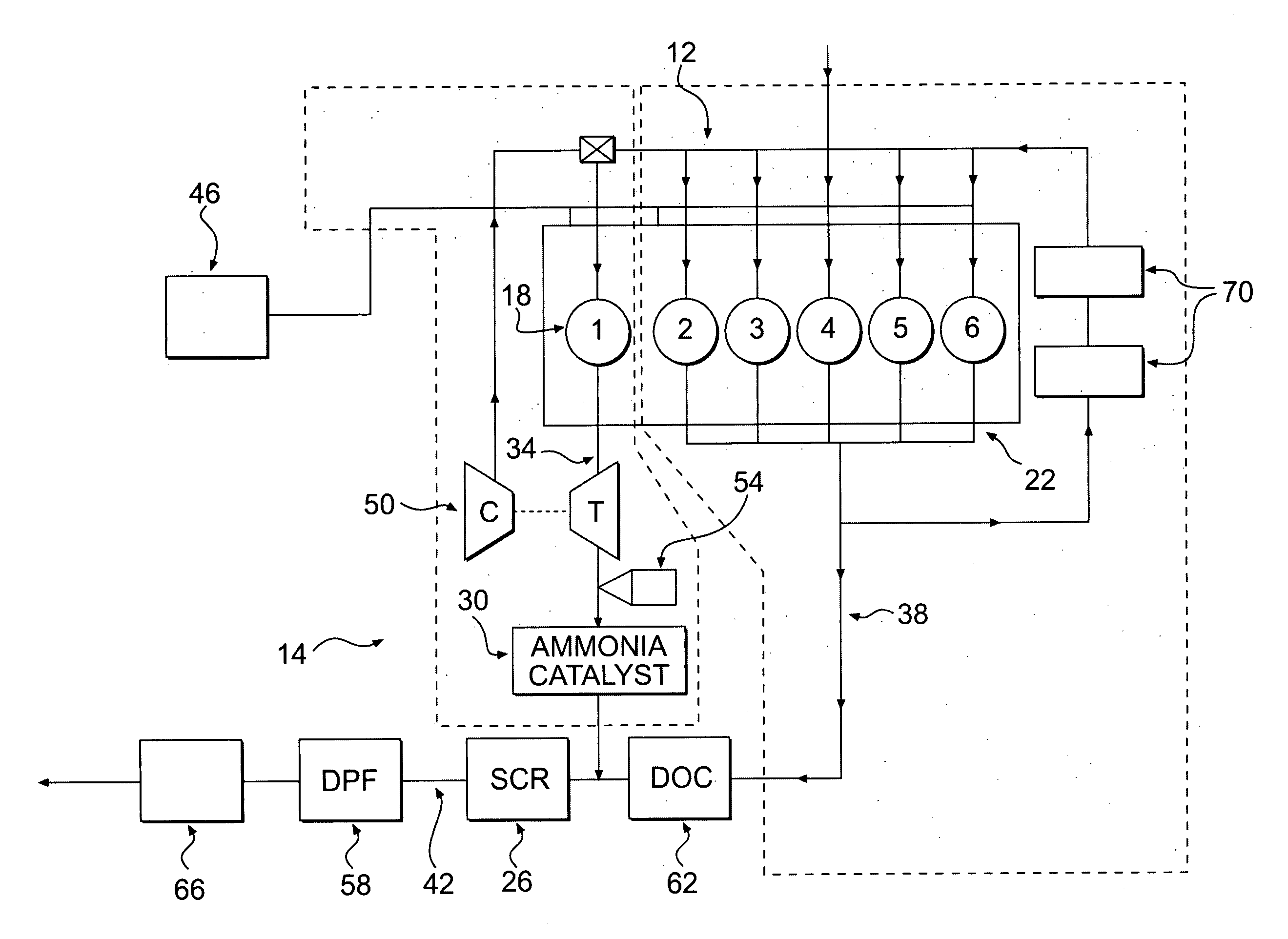
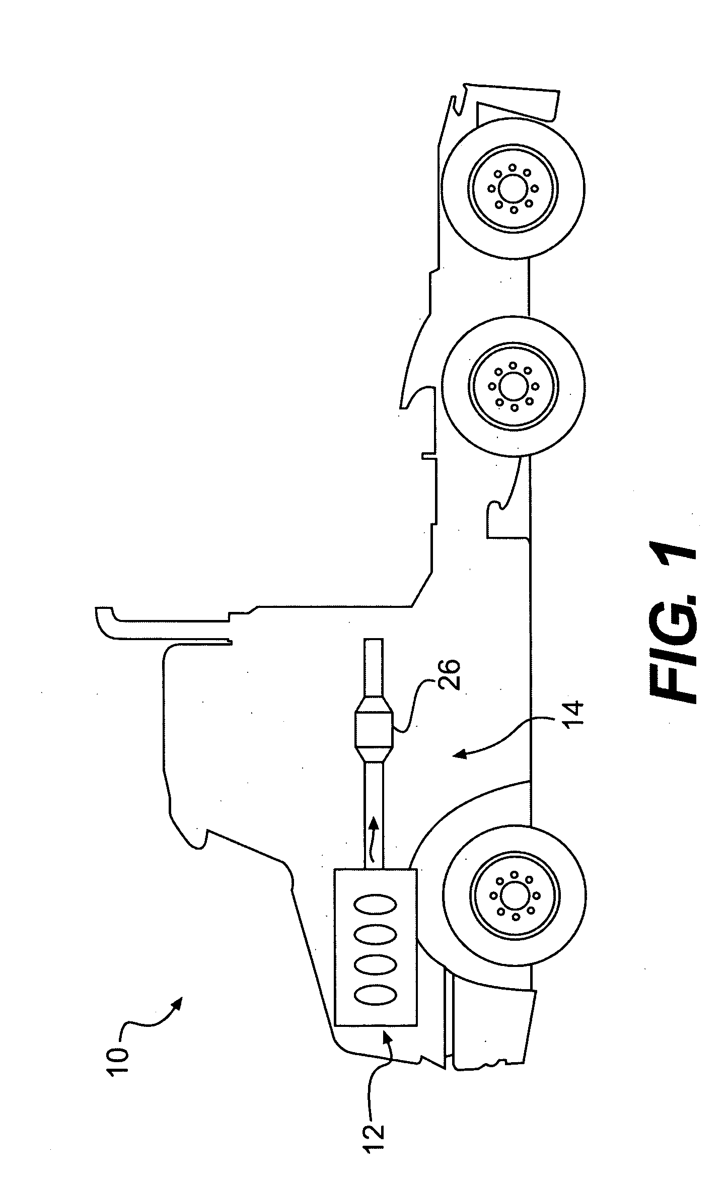
[0014]FIG. 1 illustrates a machine 10 including an engine 12 and exhaust system 14 of the present disclosure. As shown, exhaust system 14 may include one or more exhaust emissions control devices, such as a selective catalytic reduction (SCR) catalyst 26, which may be configured to control machine NOx emissions by facilitating a reaction between ammonia and NOx to remove NOx from exhaust gases produced by engine 12. Further, as described in detail below machine 10 may include systems and methods for on-board production of ammonia.

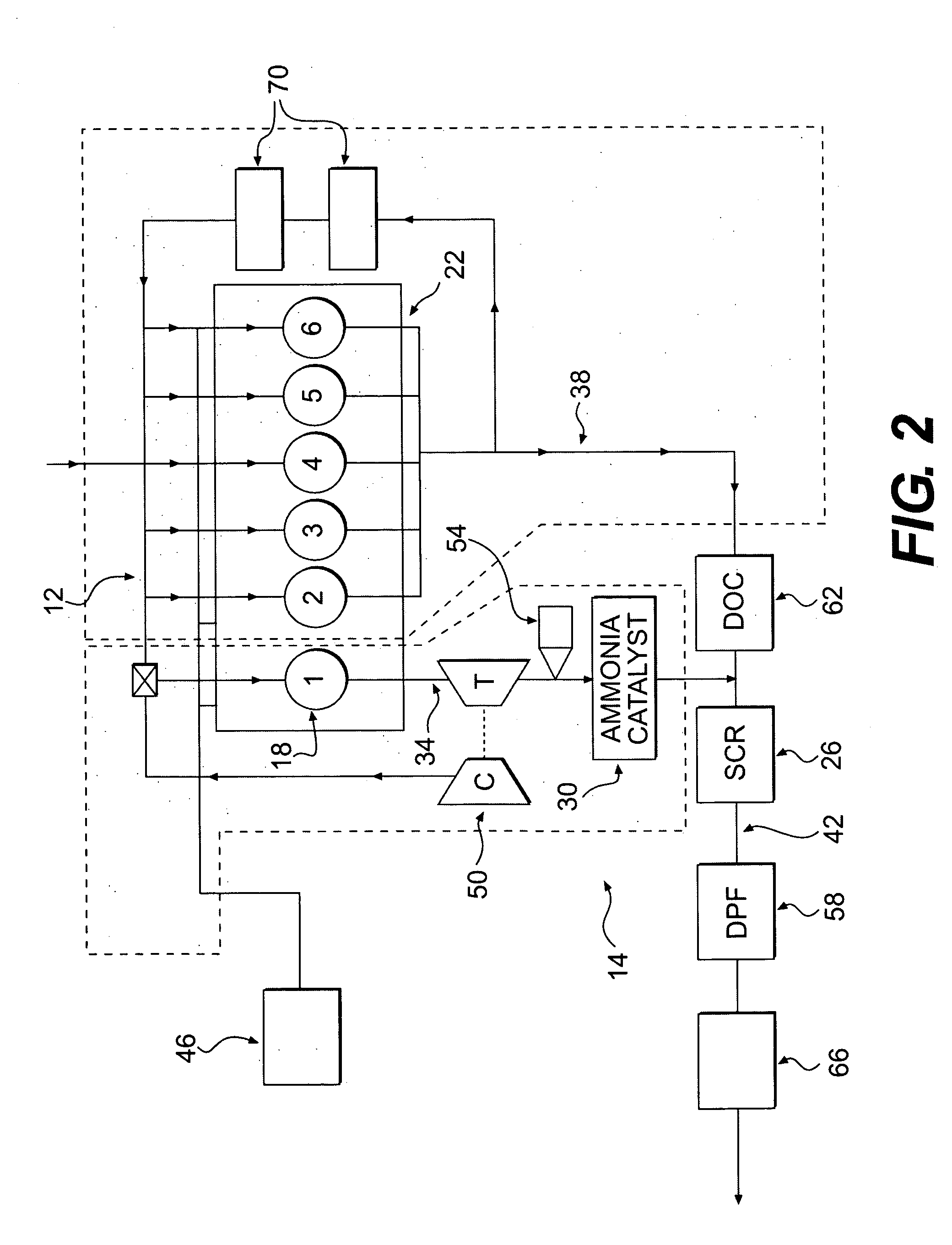
[0015]FIG. 2. provides a diagram of an engine 12 and exhaust system 14 of the present disclosure, according to an exemplary embodiment. As shown, engine 12 includes six cylinders (labeled 1-6) that are configured for combustion to produce power for machine 10. In some embodiments, engine 12 may include at least two cylinder groups 18, 22, wherein a first cylinder group 18 may include at least one cylinder 1, and a second cylinder group 22 may include two or...


PUM


Abstract

An engine is provided. The engine may comprise a first cylinder group including at least one cylinder configured to operate in a two-stroke engine operating mode and a second cylinder group including at least two cylinders configured to operate in a four-stroke engine operating mode. The power outputs of each of the cylinders in the first cylinder group and second cylinder group may be approximately equal.

Description

TECHNICAL FIELD [0001]This disclosure pertains generally to exhaust-gas purification systems for engines, and more particularly, to selective catalytic reduction systems with on-board ammonia production.BACKGROUND [0002]Selective catalytic reduction (SCR) provides a method for removing nitrogen oxides (NOx) emissions from fossil fuel powered systems for engines, factories, and power plants. During SCR, a catalyst facilitates a reaction between exhaust-gas ammonia and NOx to produce water and nitrogen gas, thereby removing NOx from the exhaust gas.[0003]The ammonia that is used for the SCR system may be produced during the operation of the NOx-producing system or may be stored for injection when needed. Because of the high reactivity of ammonia, storage of ammonia can be hazardous. Further, on-board production of ammonia can be costly and may require specialized equipment.[0004]One method of on-board ammonia production for an engine is disclosed in U.S. Pat. No. 6,047,542, issued to ...

Claims


Application Information

Patent Timeline
31 Jan 2008
Publication
US20080022666A1
IPC
F02M25/06; F01N5/04; F01N3/00; F01N3/10
CPC
F01N3/035; F01N3/106; F01N3/2073; F01N13/107; F01N2240/25; F01N2610/03; F01N13/009; F02B69/06
Inventors
DRISCOLL, JAMES J.; ROBEL, WADE J.