
Tapered optical fibers

Inactive Publication Date: 2008-01-31
HARRIS CORP
View PDF5 Cites 5 Cited by
  • Summary
  • Abstract
  • Description
  • Claims
  • Application Information

AI Technical Summary

Benefits of technology

[0012]According to yet another aspect of the invention, the method includes restoring the tension when the location transitions from the second portion to the first portion. The method also includes continuing to vary the location in the second direction of travel within the first portion. The tension is removed when the varying step in the second direction causes the location to move outside the first portion of the elongated length. When the location is within a third portion of the elongated length of the optical fiber, the second direction of travel is transitioned to the first direction of travel. This step also involves continuing to vary the location in the second direction within the third portion at the predetermined rate. It should be appreciated that the third portion of the elongated optical fiber is exclusive of the first and second portions, and while adjacent to the first portion, can have a variable length.

Problems solved by technology

The local uniformity of the waist of a tapered optical fiber limits it's usefulness in such applications.
However, these fabrication techniques suffer from certain drawbacks.
For example, the heating element and the flame do not provide uniform temperature distributions along the segment of optical fiber.
As a result, a tapered optical fiber is produced with a non-uniform waist (e.g., a waist diameter having variations of greater than one percent).
However, this fabrication technique also suffers from drawbacks.
As a result, a tapered optical fiber is produced with a non-uniform waist.

Method used


Image

  • Tapered optical fibers
  • Tapered optical fibers
  • Tapered optical fibers

Examples


Embodiment Construction

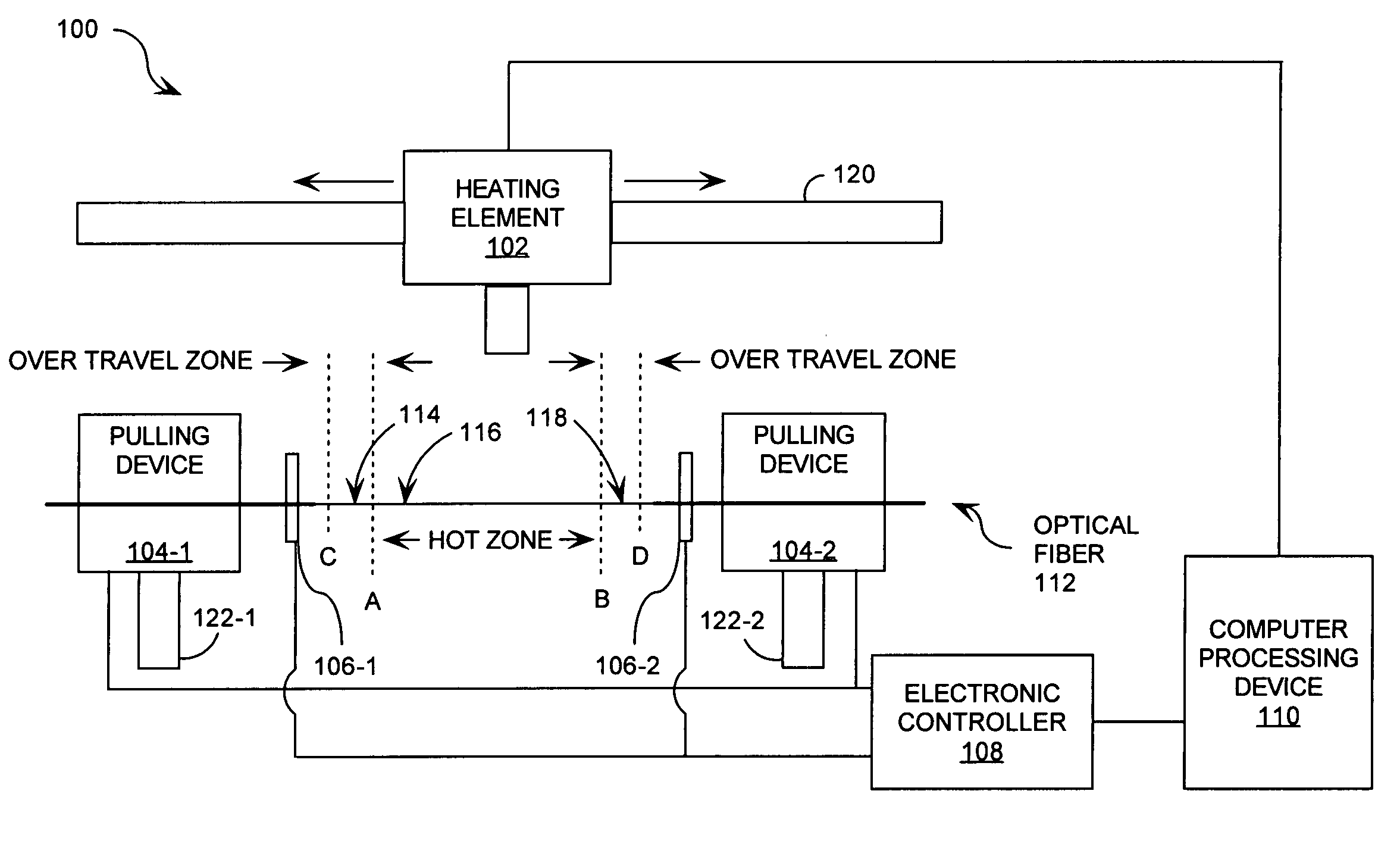
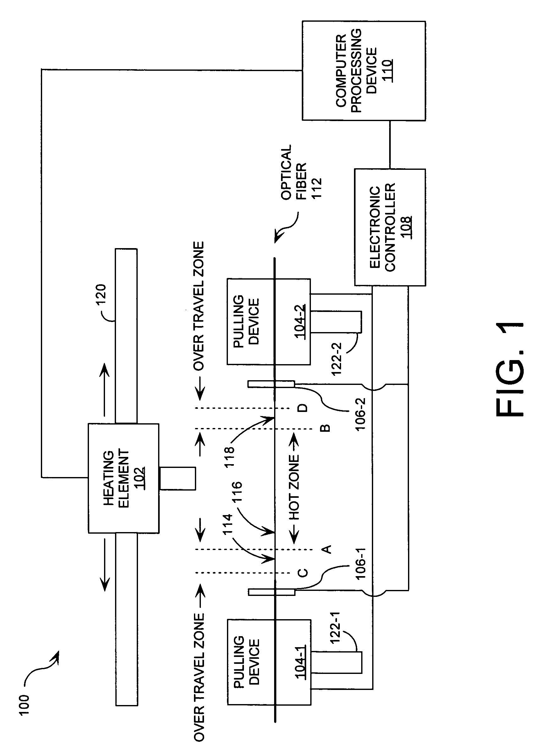
[0019]FIG. 1 is a schematic illustration of a fabrication system 100 that is useful for understanding the invention. Fabrication system 100 is comprised of a heating element 102, pulling devices 104-1, 104-2, holding mechanisms 106-1, 106-2, an electronic controller 108, and a computer processing device 110. Fabrication system 100 can secure an elongated length of an optical fiber 112 between the holding mechanisms 106-1, 106-2 while thermal energy is applied to the optical fiber 112 as hereinafter described.

[0020]Optical fiber 112 is comprised of a glass optical fiber, a plastic optical fiber, and / or a quartz optical fiber. Glass optical fibers can be formed of silica glass, fluorozirconate glass, fluoroaluminate glass, chalcogenide glass, and / or any other suitable glass known in the art. Plastic optical fibers can be formed of a transparent plastic material, such as a polymethylmeth-acrylate (PMMA) polymer.

[0021]As shown in FIG. 1, optical fiber 112 is comprised of a first portion...


PUM

PropertyMeasurementUnit
Lengthaaaaaaaaaa
Energyaaaaaaaaaa
Tensionaaaaaaaaaa

Abstract

A method for fabricating tapered optical fibers is provided. The method includes applying thermal energy at a location defined along an elongated length (114, 116, 118) of an optical fiber (112). The method also includes varying the location in a first direction of travel at a predetermined rate along the elongated length of the optical fiber while applying a tension to the optical fiber. The method further includes removing the tension when the location is outside a first portion (116) of the elongated length. According to an aspect of the invention, the method includes transitioning from the first direction of travel to a second direction of travel opposed to the first direction of travel when the location is within a second portion (114) of the optical fiber. The method further includes transitioning from the second direction of travel to the first direction of travel when the location is within a third portion (118) of the optical fiber.

Description

STATEMENT REGARDING FEDERALLY SPONSORED RESEARCH OR DEVELOPMENT[0001]This invention was made with government support. The government has certain rights in the invention as specified in Federal Acquisition Regulations FAR 52.227-12.BACKGROUND OF THE INVENTION[0002]1. Statement of the Technical Field[0003]The inventive arrangements relate to an apparatus and a method for fabricating tapered optical fibers. More particularly, this invention relates to the fabrication of tapered optical fibers having a uniform waist.[0004]2. Description of the Related Art[0005]Low loss tapered optical fibers with a uniform waist have numerous applications in fields such as telecommunications, sensor applications, and laser applications. The local uniformity of the waist of a tapered optical fiber limits it's usefulness in such applications. For example, the characteristics of light traveling through the waist depend on the local diameter. Also, filtering applications often require a highly uniform waist...

Claims


Application Information

Patent Timeline
IPC IPC(8): B29D11/00B29C67/00C03B37/02
CPCG02B6/02052G02B2006/12195G02B6/2552
Inventor HARPER, KEVIN R.DIMMICK, TIMOTHY E.DUBROFF, THEODORE E.
Owner HARRIS CORP
Learn More