Oxidation stability measurement for oil condition management

Inactive Publication Date: 2008-01-31
HONEYWELL INT INC
View PDF11 Cites 14 Cited by
  • Summary
  • Abstract
  • Description
  • Claims
  • Application Information

AI Technical Summary

Benefits of technology

[0016]It is a further aspect of the present invention to provide for an improved oil quality sensor and/or sensor array.
[0017]It is a further aspect of the present invention to provide for an improved microheater and microheater array.
[0018]It is a further aspect of the present invention to provide for an improved oil oxidation time measurement device.
[0019]It is a further aspect of the present invention to provide for an improved oxygen induction time measurement system and method.
[0020]The aforementioned aspects and other objectives and advantages can now be achieved as described herein. In a first configuration, a sensor apparatus is disclosed that includes a testing chamber configured to receive a sample of oil to be tested. A first embedded heater is coupled to the testing chamber and configured to supply heat to the sample. An oxygen flux chamber is coupled to the testing chamber and configured to provide a substantially stable oxygen flux to the testing chamber. A control module is coupled to the testing chamber, the first embedded heater, and the oxygen flux chamber. The control module is configured to monitor the temperature of the sample, direct the first embedded heater t

Problems solved by technology

Third, undesirable matter is also monitored.
Typically, undesirable matter includes solids, such as “soot” or fine carbon particles, large “agglomerated” carbon particles, and metal particles.
Over time, a lubricant's essential properties may deteriorate through a number of ways, including additive depletion, base oil oxidation, and/or contamination.
Oxidation naturally results when a lubricant is repeatedly heated up and cooled down.
The

Method used


Image

  • Oxidation stability measurement for oil condition management
  • Oxidation stability measurement for oil condition management
  • Oxidation stability measurement for oil condition management

Examples


Embodiment Construction

[0027]The particular values and configurations discussed in these non-limiting examples can be varied and are cited merely to illustrate at least one embodiment and are not intended to limit the scope thereof.

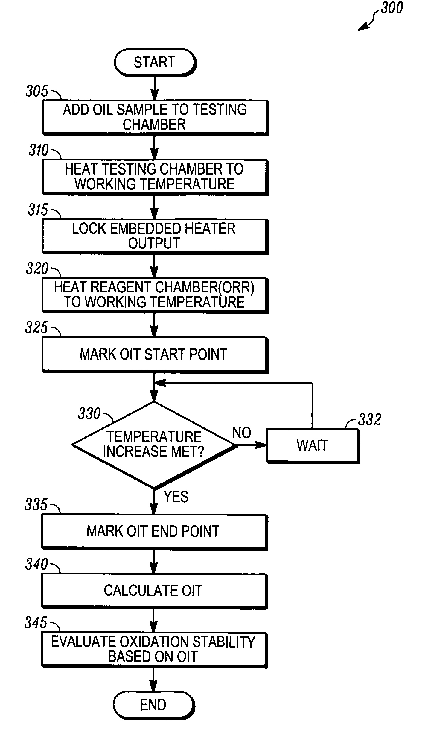
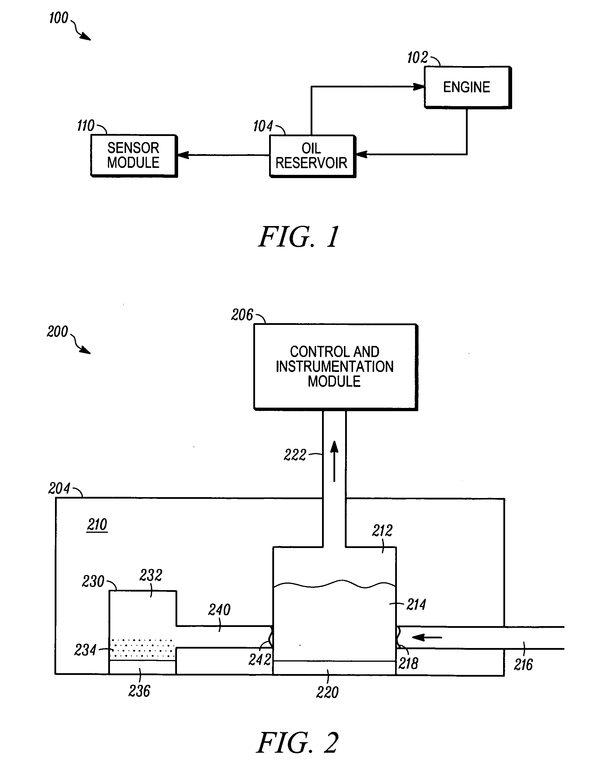
[0028]FIG. 1 illustrates a high-level oil quality management system in accordance with one embodiment of the present invention. In particular, FIG. 1 is a block diagram illustrating a sensing system, generally indicated by reference numeral 100. As described in additional detail below, the present invention allows for a means of quantifying in-use oil quality, in particular oil oxidation induction time (OIT), with improved performance over current devices on the market, which, in turn, allows for an improvement in system-wide oil quality and replacement management.

[0029]For ease of illustration, the embodiments disclosed herein are described with respect to motor / engine lubricating. One skilled in the art will understand that the embodiments disclosed herein can also be employe...


PUM


Abstract

A sensor apparatus is disclosed that includes a testing chamber or testing chamber arrays configured to receive a sample of oil to be tested. A first embedded heater is coupled to the testing chamber or testing chamber arrays and configured to supply heat to the sample. An oxygen flux chamber is coupled to the testing chamber or testing chamber arrays and configured to provide a substantially stable oxygen flux to the testing chamber. A control module is coupled to the testing chamber, the first embedded heater, and the oxygen flux chamber. The control module is configured to monitor the temperature of the sample, direct the first embedded heater to supply heat to the sample, direct the oxygen flux chamber to provide oxygen flux to the testing chamber, measure an oxygen induction time (OIT), and evaluate the oxidation stability of the sample based on the OIT. A method for thermal analysis of oil oxidation stability is also disclosed.

Description

TECHNICAL FIELD[0001]Embodiments are generally related to sensing devices and components thereof. Embodiments are also related to oil quality sensors. Embodiments are also related to microheaters and microheater arrays. Embodiments are additionally related to oil oxidation stability measurement systems and methods.BACKGROUND OF THE INVENTION[0002]Natural and synthetic lubricating oils are employed in a wide array of modern devices and systems. For example, the modern Diesel and standard internal combustion engines use lubricating oils to improve engine performance, clean engine parts, and reduce friction and heat between moving parts. Cooking oils are also used in food preparation, and in some circumstances form part of a large-scale mass-production system. Monitoring the quality and quantity of useful oils has long been a concern in the industries that employ these oils.[0003]In many modern systems, oil quality sensors are used in an integrated system for monitoring certain oil qua...

Claims


Application Information

Patent Timeline
IPC IPC(8): G01N33/26
CPCG01N33/2805
Inventor ZHOU, JI CANGWANG, WEIJUNWU, MAOSONG
Owner HONEYWELL INT INC
Why Eureka
Try Eureka