Heat dissipation device

a heat sink and heat dissipation technology, applied in the direction of lighting and heating apparatus, liquid fuel engines, instruments, etc., can solve the problems of affecting the security and performance of the system, the heat sink cannot be fixed and closely mounted into the housing, and the flanges of the sink interfere with the housing, etc., to achieve convenient assembly, avoid airflow leakage, and high heat dissipation efficiency

Inactive Publication Date: 2008-01-31
HON HAI PRECISION IND CO LTD +1
View PDF12 Cites 25 Cited by
  • Summary
  • Abstract
  • Description
  • Claims
  • Application Information

AI Technical Summary

Benefits of technology

[0005]According to a preferred embodiment of the present invention, a heat dissipation device includes a heat sink for thermally connecting with a heat-generating device and a blower for generating an airflow to the heat sink. The blower includes a housing and at least one plate extending outwardly from the housing. The housing forms a contacting surface abutting a side of the heat sink. The plate includes an inner surface abutting another side of the heat sink. A groove is defined in a junction of the housing a

Problems solved by technology

Excess heat which is not quickly removed will have disruptive influence on the system security and performance.
During assembly, the heat sink interferes with the flanges and the housing due to the chamfer angle formed at the junction of the housing and the flanges.
As a result the heat sink can not be fixedly and closely mounted into the housing.
A narrow gap may easily form between the heat sink and the housing of the blower.
Furthermore, the heat sink may inte

Method used


Image

  • Heat dissipation device
  • Heat dissipation device
  • Heat dissipation device

Examples


Embodiment Construction

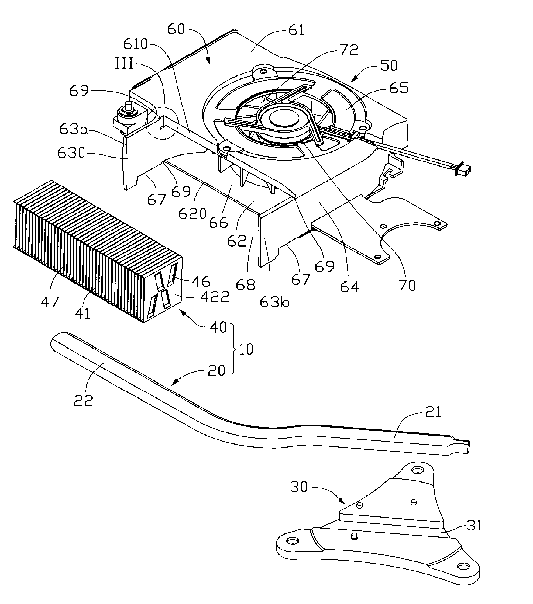
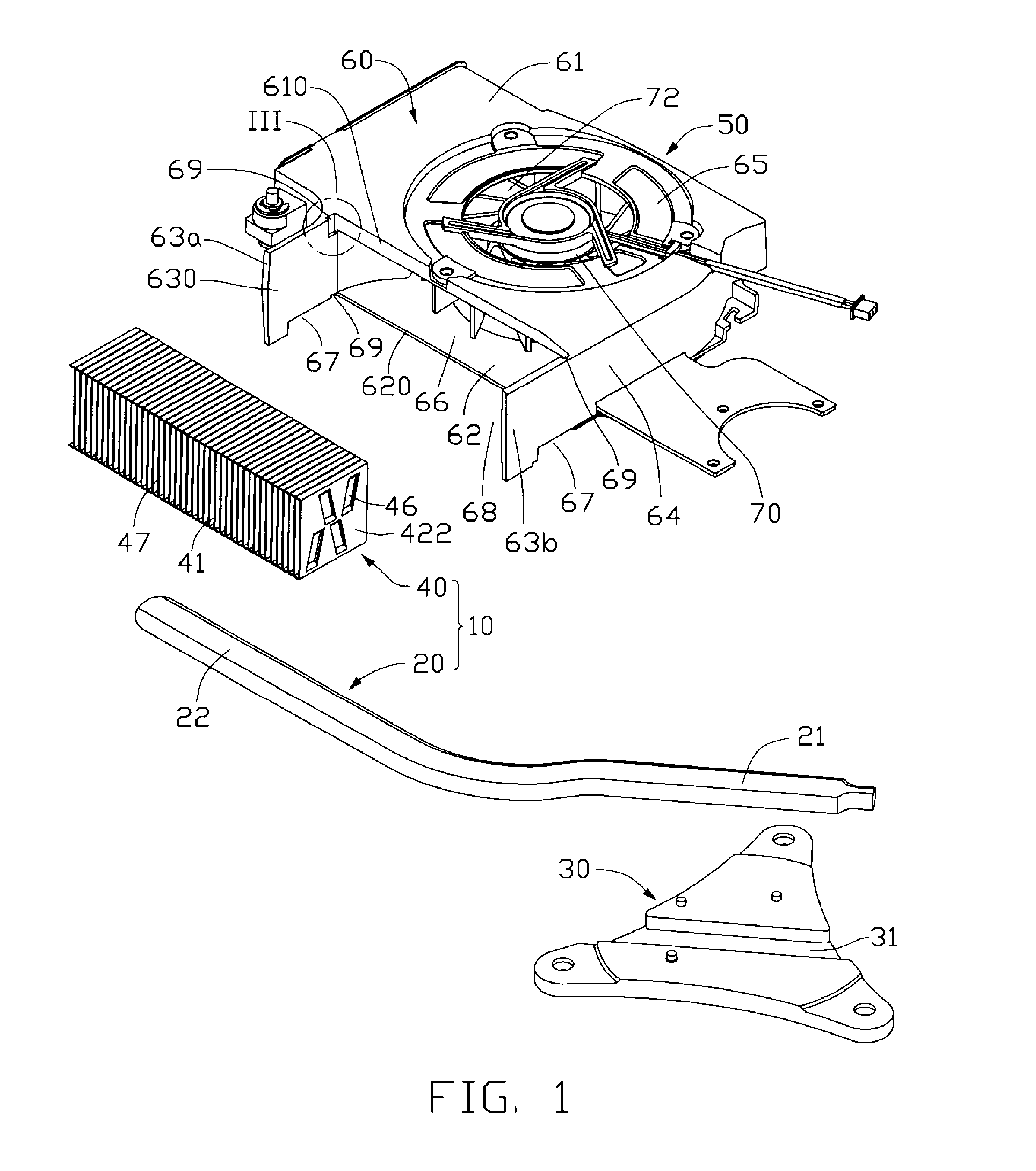
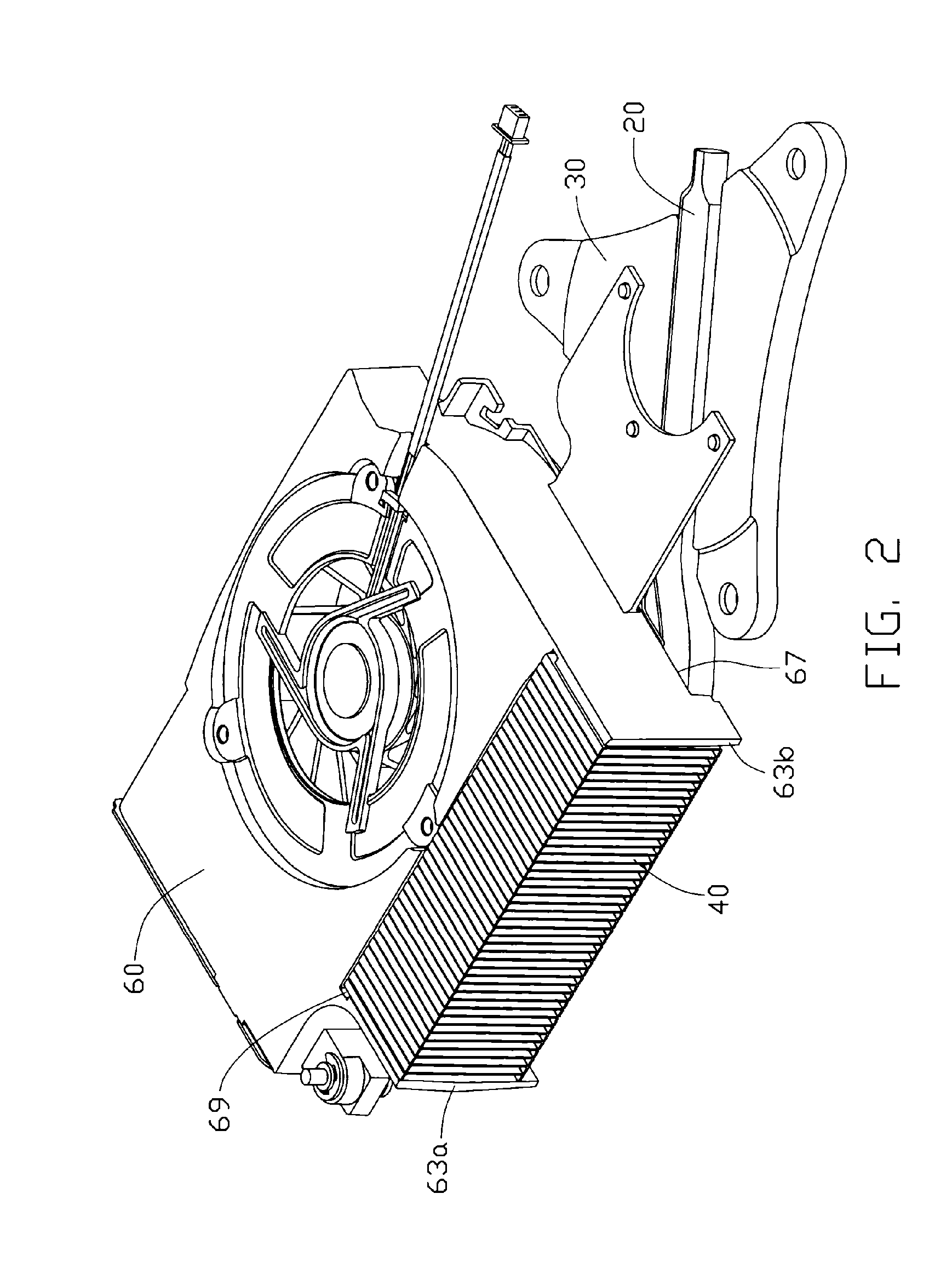
[0012]Referring to FIGS. 1-2, a heat dissipation device includes a heat sink 10 and a fan blower 50 arranged at a side of the heat sink 10. The heat sink 10 includes a fin unit 40 and a heat pipe 20 for transferring heat of a heat-generating device, for example, a central processing unit (CPU, not shown) to the fin unit 40.

[0013]The blower 50 includes a housing 60 and a motor 70 having a plurality of blades 72 extending radially and outwardly form an outer-periphery thereof. The housing 60 is integrally formed by plastic injection molding or die casting and includes a top cover 61 arranged at a top side of the motor 70, a bottom cover 62 arranged at a bottom side of the motor 70 parallel to the top cover 61, and a sidewall 64 interconnecting between the top and bottom covers 61, 62 and surrounding the motor 70. The two covers 61, 62 and the sidewall 64 co-operatively define a space (not labeled) for receiving the motor 70 therein. An air inlet 65 is defined in a central portion of t...


PUM


Abstract

A heat dissipation device includes a heat sink (10) and a blower (50) for generating an airflow to the heat sink. The blower includes a housing (60) and at least one plate (63a, 63b) extending outwardly from the housing. The housing forms a contacting surface (610, 620) abutting a side of the heat sink. The plate includes an inner surface (630) abutting another side of the heat sink. A groove (69) is defined in a junction of the housing and the plate, and thus the contacting surface of the housing and the inner surface of the plate are planar-shaped to avoid interference between the housing of the blower and the heat sink. The groove has chamfer angles R therein. The housing is made by plastic injection molding or die casting.

Description

FIELD OF THE INVENTION[0001]The present invention relates generally to a heat dissipation device, and in particular to a heat dissipation device with improved fan housing which a heat sink can be conveniently mounted on.DESCRIPTION OF RELATED ART[0002]With the advance of large scale integrated circuit technology, and the widespread use of computers in all trades and occupations, in order to meet the required improvement in data processing load and request-response times, high speed processors have become faster and faster, which causes the processors to generate excess heat. Excess heat which is not quickly removed will have disruptive influence on the system security and performance. Usually, a heat sink is installed on the central processor to assist its heat dissipation, whilst a cooling fan is also used to provide a forced airflow which increases heat dissipation.[0003]A blower is more suitably used in a notebook since it has a flat configuration and a large air flow rate. The b...

Claims


Application Information

Patent Timeline
IPC IPC(8): H05K7/20
CPCF04D29/582G06F1/203H01L23/3672H01L23/467H01L2924/0002H01L2924/00
Inventor PENG, JIE-BOMENG, JIN-GONGHWANG, CHING-BAIHUNG, JUI-WEN
Owner HON HAI PRECISION IND CO LTD
Why Eureka
Try Eureka