

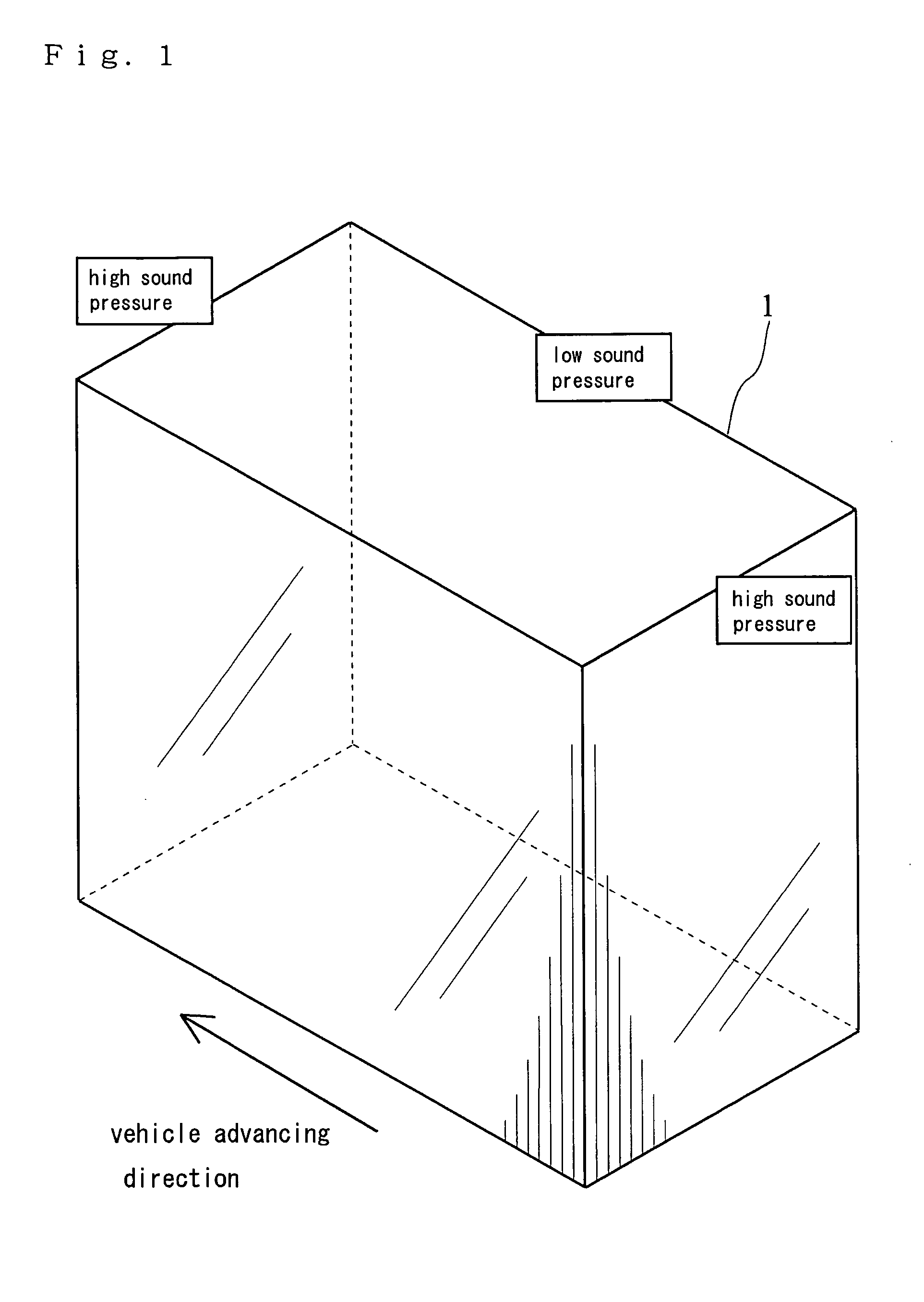
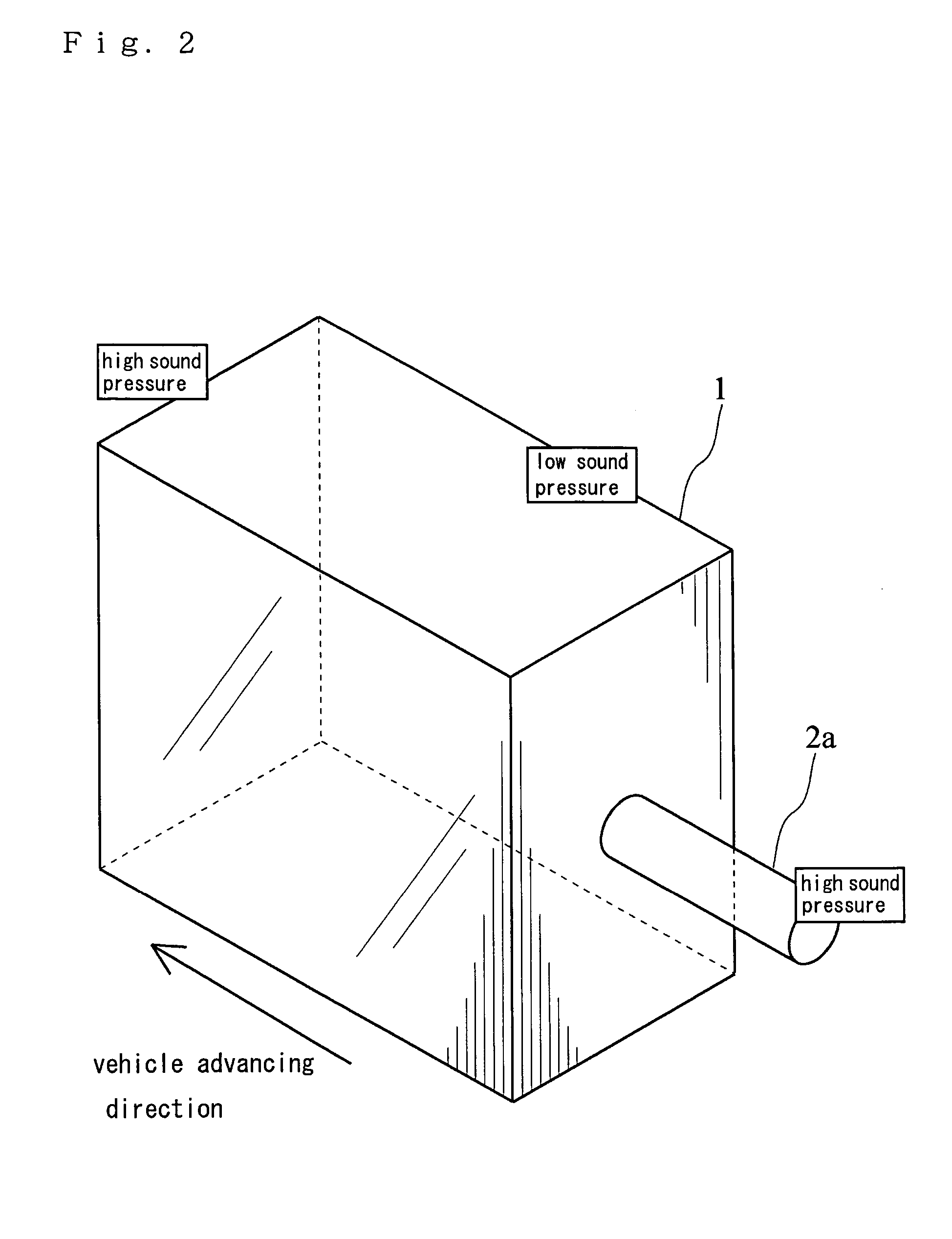
Noise Proof Structure of Cabin
a technology of noise proof structure and cabin, which is applied in the direction of doors, machines/engines, instruments, etc., can solve the problems of difficult to sense the change of the frequency of the vibration generator, the obstruction of the partition or the like in the cabin, and the difficulty of substantially changing the dimensions of the cabin, so as to prevent the increase of the noise caused by hollow resonance, reduce the effect of furry noise and efficient reduction of the resonance phenomenon
- Summary
- Abstract
- Description
- Claims
- Application Information
AI Technical Summary
Benefits of technology
Problems solved by technology
Method used
Image

Examples
second embodiment
[0153] Next, explanation will be given on the second embodiment concerning the noise proof structure of the cabin according to the present invention. The furry noise may not be reduced to the desired level though the resonator 23 is disposed to the cabin of the working machine or the like. In this case, as shown in FIG. 8, a resonator 25 having the same resonance frequency and larger volume is attached to the cabin 1 so as to be able to be exchanged, whereby transfer amount of the frequency is increased.
[0154] Herein, when a Helmholtz type resonator 26 is disposed to the cabin 1 as shown in FIG. 9, an opening 26a of the resonator 26 is also changed corresponding to the volume of the resonator 26.
[0155] The resonance pipe or the resonance box can be exchanged with the resonance pipe or the resonance box 26 having the same resonance frequency and different volume.
[0156] Accordingly, by increasing the amount of movement of the frequency following the increase of volume, the resonance...
third embodiment
[0157] Next, explanation will be given on an opening of a Helmholtz type resonator 27, which connects the cabin 1 to the resonator 27, as the third embodiment according to FIGS. 10 to 13.
[0158] As shown in FIGS. 10 and 11, a partition 41 is disposed at the opening of the resonator 27 so as to be able to be opened and closed. For making the partition 41 able to be opened and closed, the partition 41 may be slide type or be a pivoted door centering on the edge of the opening. Accordingly, the partition 41 is opened and closed.
[0159] Well, resonance frequency fs of a side branch type resonator is explained by below formula.
fs=C / 4l
[0160] C=sound velocity, l=length (depth) of resonator
[0161] Resonance frequency fh of a Helmholtz type resonator is explained by below formula.
fh=(C / 2π)*(A / Vl) / 2
[0162] C=sound velocity, A=area of opening, l=equivalent length (depth) of neck of resonator, V=volume of resonator
[0163] Accordingly, in the case of disposing the Helmholtz type resonator 27 t...
fourth embodiment
[0168] Next, explanation will be given on the fourth embodiment concerning the noise proof structure of the cabin according to the present invention.
[0169] An operator in the cabin may open and close the partition 41 directly. However, as shown in FIGS. 12 and 13, it may alternatively be constructed so that one of ends of a wire 43 is connected to an accelerator 42 controlling the rotary speed of the engine and the other end thereof is connected to the partition 41, whereby the area A of the opening is changed corresponding to the rotary speed.
[0170] When the rotary speed of the engine is increased, the vibrating frequency is also increased. When the rotary speed of the engine is decreased, the vibrating frequency is also decreased. Accordingly, the wire 43 is connected so that the area A of the opening is increased by treading an accelerator pedal and the area A of the opening is decreased by releasing an accelerator pedal. Otherwise, the resonator may be constructed to be opened ...
PUM
 Abstract
Description
Claims
Application Information