Magnetic head

a head and magnet technology, applied in the field of magnet head, can solve the problems of large heat influence on read element and write element, inability to efficiently heat and protrude, and inability to set the flying height smaller than the common differences, so as to improve the heater efficiency, and improve the heater efficiency.

Inactive Publication Date: 2008-01-31
TOSHIBA STORAGE DEVICE CORP
View PDF11 Cites 13 Cited by
  • Summary
  • Abstract
  • Description
  • Claims
  • Application Information

AI Technical Summary

Benefits of technology

[0027]Therefore, the protruding distance of the medium facing surface in a high-temperature environment and under worst conditions in which write electric power is large can be suppressed. Since the protruding distance under the worst conditions is suppressed, even in the structure in which the low thermal conducting layer is provided to enhance heater efficiency, the set value of the clearance which is set for avoiding collision with the medium surface is not required to be large, and the medium facing surface can be protruded at good heater efficiency without increasing the heater electric power.
[0028]Another mode of the present invention is mainly for improving the heater efficiency, and the low thermal conducting layer made of a material having a low thermal conductivity is disposed in the path through which the heat caused by electric power distribution to and heating of the heater coil transmits in the substrate side. As a result, the heat caused by electric power distribution to and heating of the heater coil can be sealed in the medium facing surface side in which the recording element (write gap) and the reading element (read gap) are present so as to sufficiently and centrally heat the write coil, and the heater efficiency can be enhanced by causing the medium facing surface to protrude by smal...

Problems solved by technology

However, there are problems that collision with minute protrusions on the magnetic disk surface readily occur when the flying height of the magnetic head is reduced, and variations in the clearance of heads are present in the range of common differences of mechanisms; therefore, when contact with the medium is taken into consideration, flying heights smaller than the common differences cannot be set.
Such conventional magnetic head in which the heater is incorporated has a problem that the heat generated by electric power distribution to a heater coil is transmitted to the substrate side of the magnetic head, which is formed as a slider, and dissipated to the medium facing surface, and the medium facing surface side in which a write gap which functions as a recording element of a write head and a read gap where a reading element is disposed are disposed cannot be efficiently heated and protruded.
However, there is a problem that, when the temperature of the heater coil is excessively increased by the electric power distribution, migration of the heater coil and influence of heat on a read element and a write element become large, and du...

Method used


Image

  • Magnetic head
  • Magnetic head
  • Magnetic head

Examples


Embodiment Construction

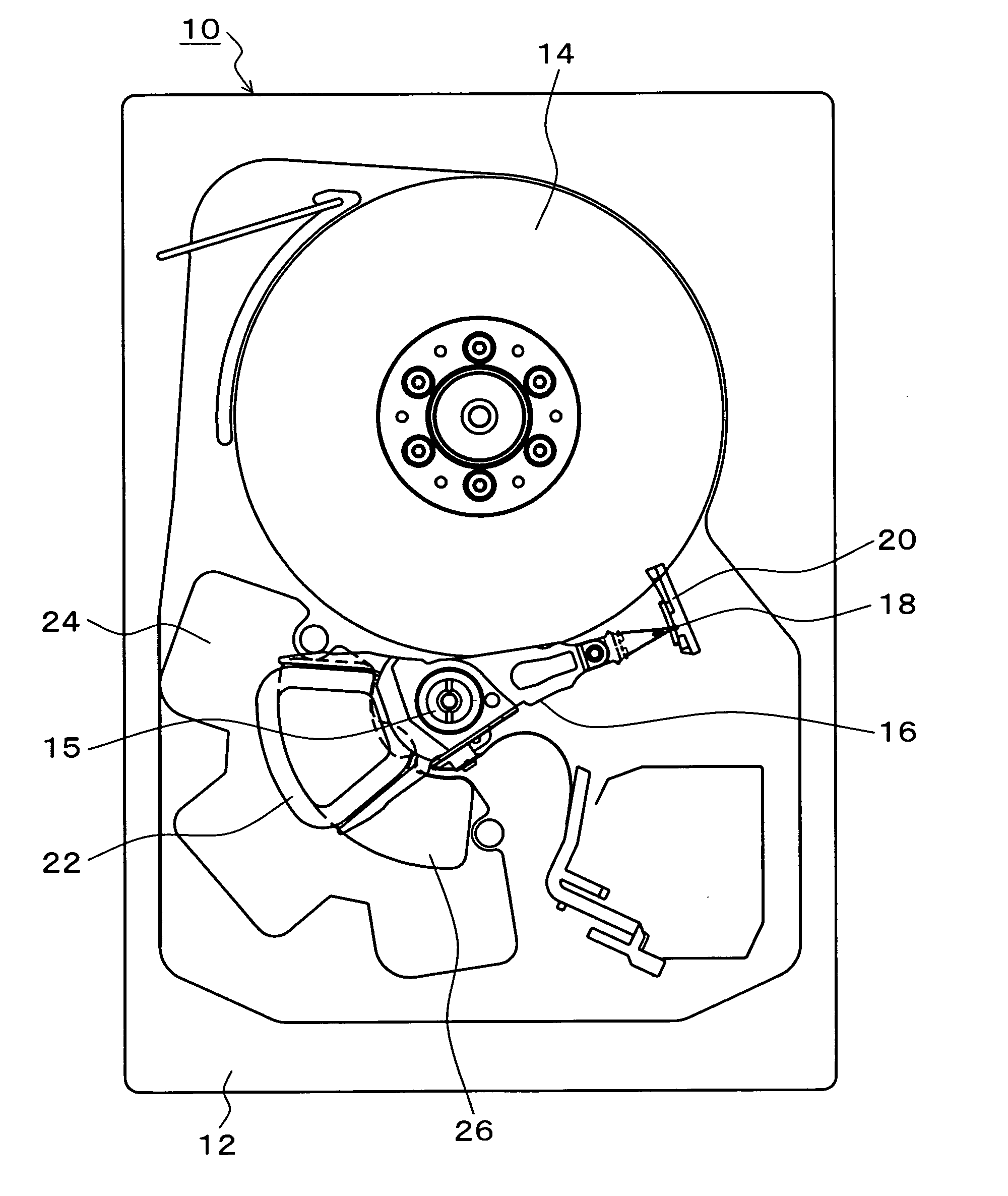
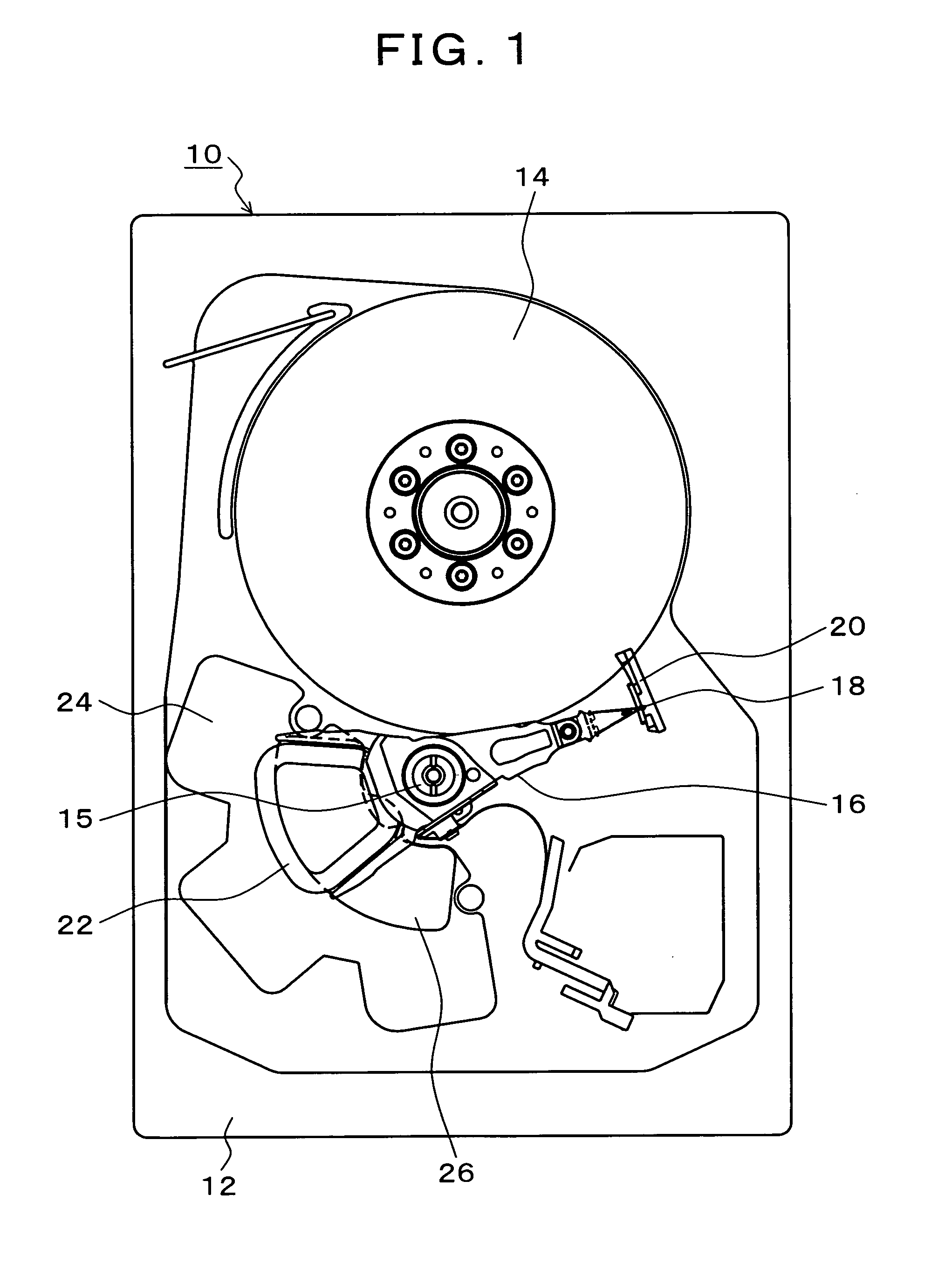
[0046]FIG. 1 is an explanatory drawing of a magnetic disk apparatus in which a magnetic head of the present invention is used. In FIG. 1, in the magnetic disk apparatus 10, the internal structure of a chassis base 12 from which a chassis cover is removed is shown. In the chassis base 12, a magnetic disk 14 which is rotated by a spindle motor at a constant speed is provided, and, for the magnetic disk 14, a rotary actuator 16 is rotatably disposed by a shaft unit 15. The rotary actuator 16 supports the magnetic head according to the present invention by the distal end thereof, and a coil 22 is disposed in a rear part thereof. The coil 22 is rotatable along a magnet 26 on a lower yoke 24 which is fixed to the chassis base 12 side. Although an upper yoke which is not shown and has the same shape as the lower yoke 24 is disposed above the coil 22, the state in which the upper yoke is removed is shown in the present embodiment. A magnetic circuit unit is formed by the lower yoke 24, the ...


PUM


Abstract

A magnetic head has a read head in which a read element which converts recording magnetic flux emitted from the magnetic disk into an electric signal is disposed between a pair of shield layers on a substrate, and magnetically records information by emitting magnetic flux generated by a write current flowing through a write coil from a magnetic pole unit to a magnetic disk. A heater coil is disposed to face the write coil via an insulating layer, and a medium facing surface is caused to protrude toward the recording medium side by thermal expansion caused by electric power distribution and heating. Subsequent to the shield layer in the substrate side, a low thermal conducting layer made of a material having a low thermal conductivity which suppresses transmission of the heat caused by electric power distribution to and heating of the heater coil and a low thermal expansion layer which is disposed in the substrate side of the low thermal conducting layer and is made of a material having a low thermal expansion coefficient are disposed.

Description

[0001]This application is a priority based on prior application No. JP 2006-204313, filed Jul. 27, 2006, in Japan.BACKGROUND OF THE INVENTION[0002]1. Field of the Invention[0003]The present invention relates to a magnetic head which can control the clearance between a head and a recording medium by varying the protruding distance of a medium facing surface by thermal expansion accompanying power distribution to and heating of a heater coil, and particularly relates to a magnetic head which can obtain a large protruding distance of a medium facing surface by a little electric power of a heater coil.[0004]2. Description of the Related Arts[0005]Conventionally, the flying height of a magnetic head with respect to a recording surface of a magnetic disk has to be reduced in order to realize a high recording density of a magnetic disk apparatus; and, recently, flying heights of 10 nm order have been realized. However, there are problems that collision with minute protrusions on the magnet...

Claims


Application Information

Patent Timeline
IPC IPC(8): H05B6/16
CPCB82Y10/00B82Y25/00G11B5/3136G11B5/314G11B2005/3996G11B5/3912G11B5/3967G11B5/5552G11B5/6011G11B5/3909G11B5/127G11B5/31G11B5/60G11B21/21
Inventor AOKI, KENICHIRONAKADA, TOSHIYUKI
Owner TOSHIBA STORAGE DEVICE CORP
Why Eureka
Try Eureka