Encoder-equipped sealing device

a sealing device and encoder technology, applied in the direction of brake systems, instruments, transportation and packaging, etc., can solve the problems of affecting the mounting efficiency of the mounting machine, the mounting machine cannot work well, and the unit is difficult to handle, so as to achieve the effect of better sealing capability

Inactive Publication Date: 2008-01-31
YAMAMOTO
View PDF12 Cites 7 Cited by
  • Summary
  • Abstract
  • Description
  • Claims
  • Application Information

AI Technical Summary

Benefits of technology

[0019] Several units of the encoder-equipped sealing device according to the present invention, such as two units in this case, may be stored in a mounting magazine before they are actually mounted on an area that needs to be sealed, such as a bearing unit. Within the magazine, the two units may be placed one over the other so that they can be oriented in one particular direction as shown in FIG. 3. When the units are placed in the magazine, the encoder of one unit can always be separated by the elastic element of the other unit that is placed adjacently the one unit. In other words, the elastic element may always be placed between the encoder of the one unit and the flange portion of the reinforcing ring of an adjacent unit. Thus, there is no magnetic cohesion between the two units placed one over the other and oriented in one particular direction that would be caused by magnetic attraction of the encoder of one of these two adjacent units. When an attempt is then made to remove one unit from the magazine, that contains the two units placed in such a manner as to be oriented in one particular direction, and then to mount the unit onto a bearing unit, this can be done easily by simply sliding the unit vertically or horizontally with regard to the other unit. Thus, the encoder-equipped sealing device can be mounted with highly improved reliability onto a bearing unit by any mechanical device.
[0020] In accordance with a first aspect of the encoder-equipped sealing device according to the present invention, the elastic element formed on and supported by the flange portion of the before described other seal member may be formed to have a thickness that becomes greater from one end toward another end of the flange portion of the before described other seal member. The elastic element thus formed includes a thickened part that can prevent magnetic cohesion from occurring between the two units. It may be seen from FIG. 2 that the elastic element thus formed has a surface that is slanted smoothly and with no undulations from one end of the flange portion toward the other end thereof. Thus, the units that are placed in such a manner as to be oriented in one particular direction within the mounting magazine can be removed easily from the magazine by simply sliding one unit vertically or horizontally with regard to the other unit, and can then be mounted onto the bearing unit. When an attempt is thus made to remove the units in order to mount them on the bearing unit, this can be accomplished easily without causing the units to be stuck or caught by some parts within the magazine.
[0022] In addition to the function and effect that may be provided by the encoder-equipped sealing device according to the first aspect, the encoder-equipped sealing device according to the second aspect can provide a better sealing capability for a bearing unit because the forward end is formed to have a greatest thickness and project beyond the other end of the flange portion when the encoder-equipped sealing device is mounted on the bearing unit.

Problems solved by technology

In other words, the mounting machine cannot work well, which may introduce a serious problem of affecting a mounting efficiency of the mounting machine considerably.
By so doing, however, it would be difficult to handle the units.
For this reason, this method had a short life.

Method used


Image

  • Encoder-equipped sealing device
  • Encoder-equipped sealing device
  • Encoder-equipped sealing device

Examples


Embodiment Construction

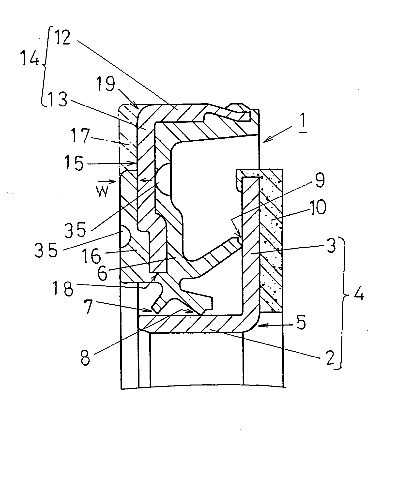
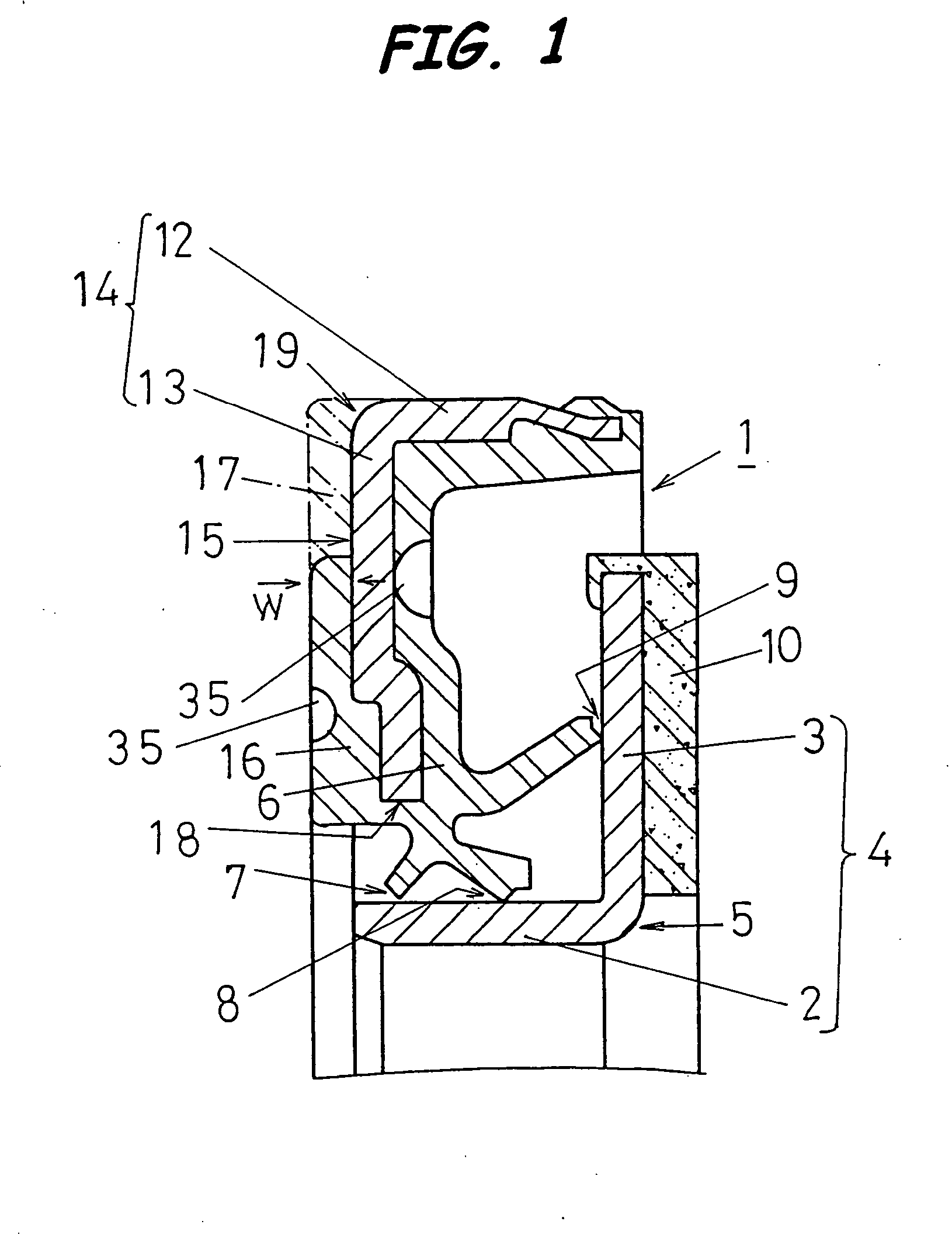
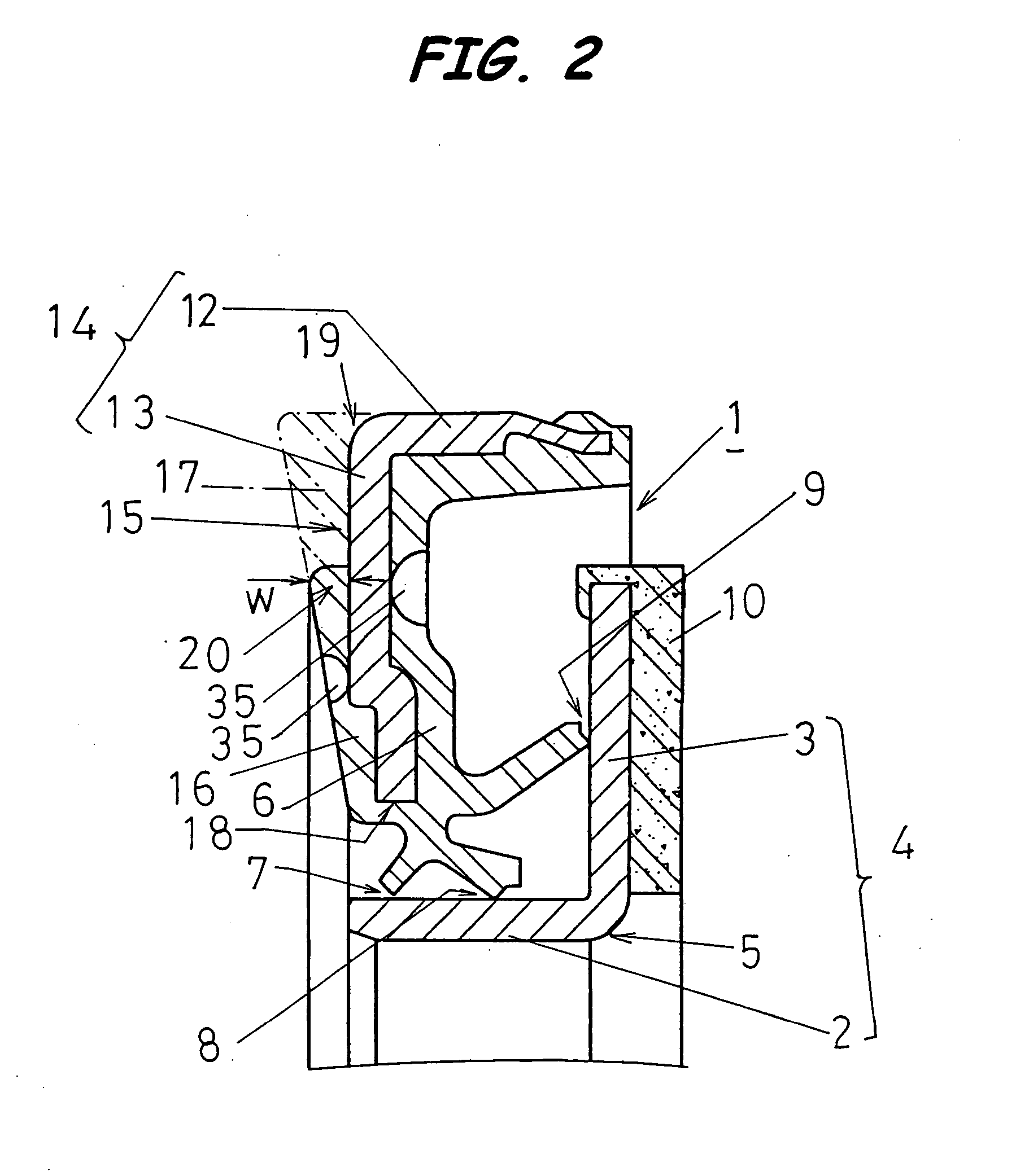
[0030] Referring now to FIG. 1, an encoder-equipped sealing device according to one embodiment of the present invention, generally identified by 1, includes two seal members 5, 15 combined together such that they are arranged to face opposite each other.

[0031] Specifically, the seal member 5 includes a reinforcing ring 4 with an L-shaped cross section having a cylindrical portion 2 and a flange portion 3 extending from one end of the cylindrical portion 2 in a direction perpendicular to the cylindrical portion 2.

[0032] Similarly, the seal member 15 includes a reinforcing ring 14 with an L-shaped cross section having a cylindrical portion 12 and a flange portion 13 extending from one end of the cylindrical portion 12 in a direction perpendicular to the cylindrical portion 12.

[0033] The seal member 15 further includes an elastic seal 6 formed such that it can be supported by the reinforcing ring 14. In the encoder-equipped sealing device 1 that has been completed as described above...


PUM

PropertyMeasurementUnit
thicknessaaaaaaaaaa
lengthaaaaaaaaaa
thicknessaaaaaaaaaa

Abstract

An encoder-equipped sealing device includes two seal members arranged to face opposite each other and each having a reinforcing ring with an L-shaped cross section. Each of the reinforcing rings has a cylindrical portion and a flange portion extending from one end of the cylindrical portion in a direction perpendicular to the cylindrical portion. One seal member includes an elastic seal formed in such a manner as to be supported by the reinforcing ring of this seal member, with the elastic seal extending toward the other seal member such that a seal portion is formed between the elastic seal and the other seal member. The other seal member includes an encoder on a side of the flange portion of the other seal member that is opposite a side facing the one seal member. The one seal member includes an elastic element formed in such a manner as to be supported by the flange portion of this seal member. The elastic element is formed on a side of the flange portion of the one seal member that is opposite a side facing the other seal member.

Description

[0001] This application is a continuation application of Ser. No. 11 / 496,466, filed Aug. 1, 2006, which is a continuation application of Ser. No. 10 / 484,166, filed Jan. 20, 2004, which is a National Stage of PCT / JP02 / 07297, filed Jul. 18, 2002.TECHNICAL FIELD [0002] Generally, the present invention relates to an improvement to or in a sealing device with an encoder, that is, an encoder-equipped sealing device. More particularly, the present invention relates to such encoder-equipped sealing device that may be mounted on a bearing unit for supporting a wheel on an automotive vehicle so that the sealing device can seal the bearing unit by isolating an interior thereof from an exterior thereof, wherein the encoder that is incorporated into the encoder-equipped sealing device may be located to face opposite a rotation detecting sensor that responds to the encoder for detecting a number of revolutions of the wheel when the encoder-equipped sealing device is mounted on the bearing unit. B...

Claims


Application Information

Patent Timeline
Patent Type & Authority Applications(United States)
IPC IPC(8): F16J15/32G01N33/18B60T8/171C02F1/00F16C33/78F16C41/00F16J15/00F16J15/326G01N5/02G01P3/44G01P3/487
CPCF16C33/7879F16C41/007F16J15/002F16C2326/02F16J15/3264G01P3/443G01P3/487F16J15/326
Inventor YAMAMOTO, HIRONORI
Owner YAMAMOTO
Why Eureka
Try Eureka