
Motor protection system

a protection system and motor technology, applied in the direction of motor/generator/converter stopper, emergency protection arrangement responsive to undesired changes, dynamo-electric converter control, etc., can solve the problem of difficult to suitably estimate the temperature, the temperature of plural components cannot be easily estimated by only one arithmetic expression, etc. problem, to achieve the effect of preventing overheating of the motor

Inactive Publication Date: 2008-01-31
HONDA MOTOR CO LTD
View PDF5 Cites 29 Cited by
  • Summary
  • Abstract
  • Description
  • Claims
  • Application Information

AI Technical Summary

Benefits of technology

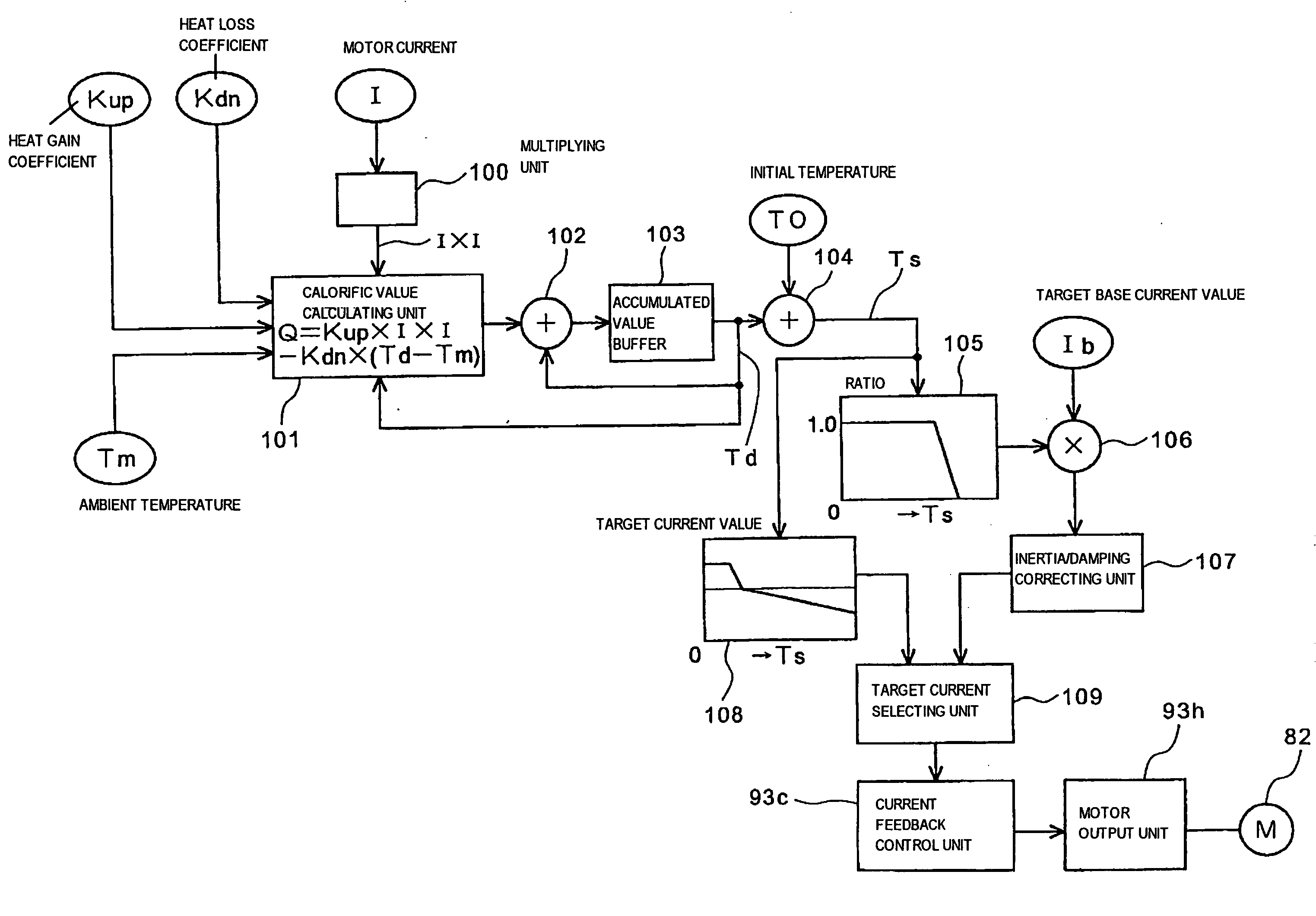
[0016]The object of the invention is to provide a motor protection system in which the temperature of an electric motor is precisely estimated and the overheating of the motor can be prevented in a power steering system used under a driving condition wherein the power steering system is frequently operated and during other driving conditions.

Problems solved by technology

The above-mentioned Expression 2 is suitable for a vehicle that dedicatedly runs on a maintained general road, however, it is not necessarily suitable for an all terrain vehicle (ATV) that runs off road and on other terrain.
However, when the heat capacity of each component is different, it is difficult to suitably estimate the temperature, for example, a component is estimated to be slightly overheated and a protection measure such as the limitation of current is sometimes taken soon.
In addition, as not only heat capacity but heat resistant temperature are different for every component, the temperature of plural components cannot be easily estimated by only one arithmetic expression.

Method used


Image

  • Motor protection system
  • Motor protection system
  • Motor protection system

Examples


Embodiment Construction

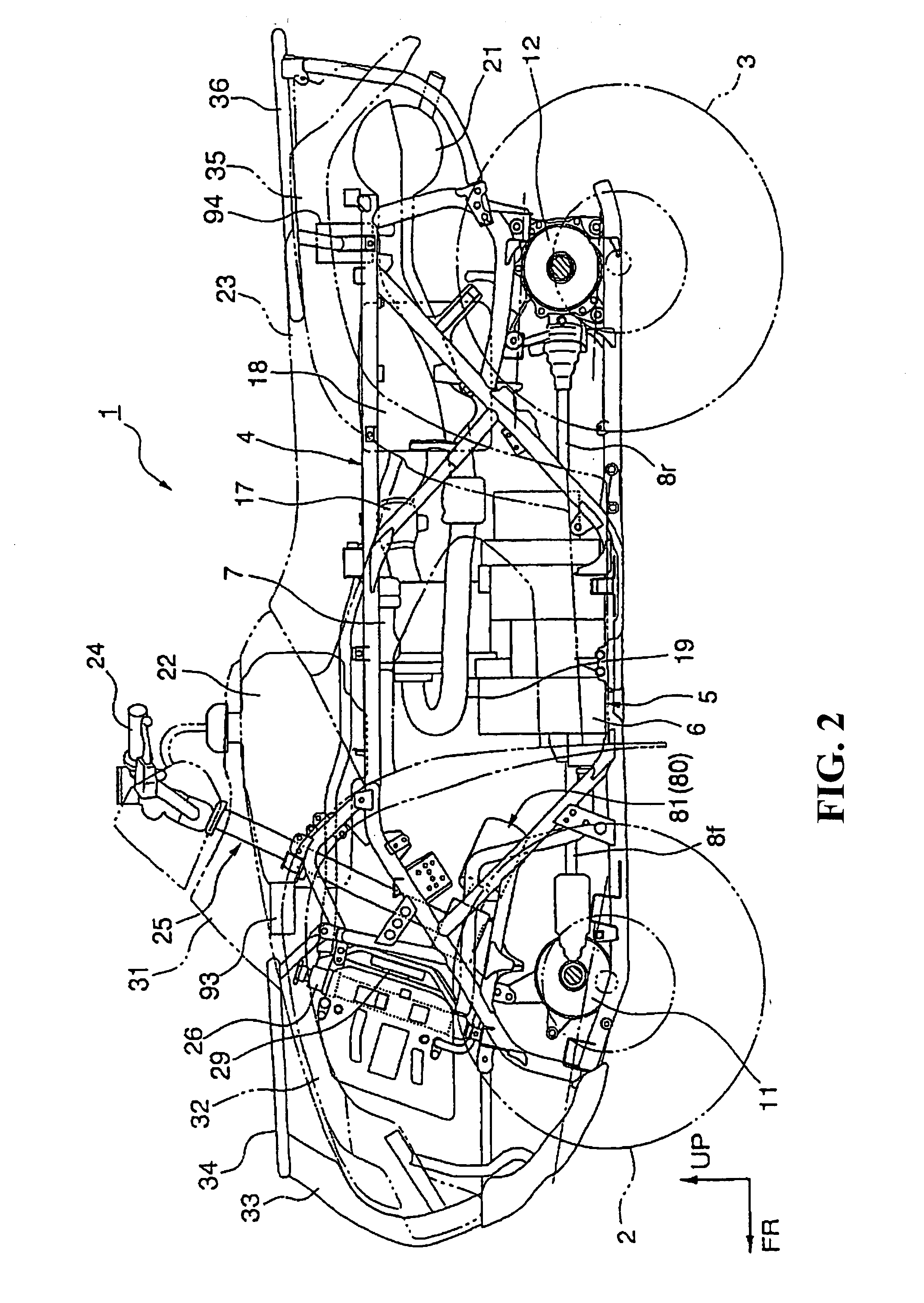
[0065]Referring to the drawings, one embodiment of the invention will be described below. FIG. 2 is a left side view showing a saddle-ride type vehicle in which a control unit for electric power steering equivalent to one embodiment of the invention is built. The saddle-ride type vehicle (hereinafter merely called the vehicle) 1 is provided with right and left front wheels 2 and back wheels 3 which are low pressure balloon tires having a relatively large diameter in a longitudinal direction of a compact and light body. Vehicle 1 is an all terrain vehicle (ATV) that is capable of driving on an uneven road.

[0066]An engine 5 as a power plant is mounted in the center of a body frame 4. The engine 5 is a water-cooled single-cylinder engine and is laid out so that its output shaft is located in a longitudinal direction of the vehicle 1. A transmission shaft 8f protruded forward from a lower part of the engine 5 and is connected to the front wheel 2 via a front speed reducing mechanism 11 ...


PUM


Abstract

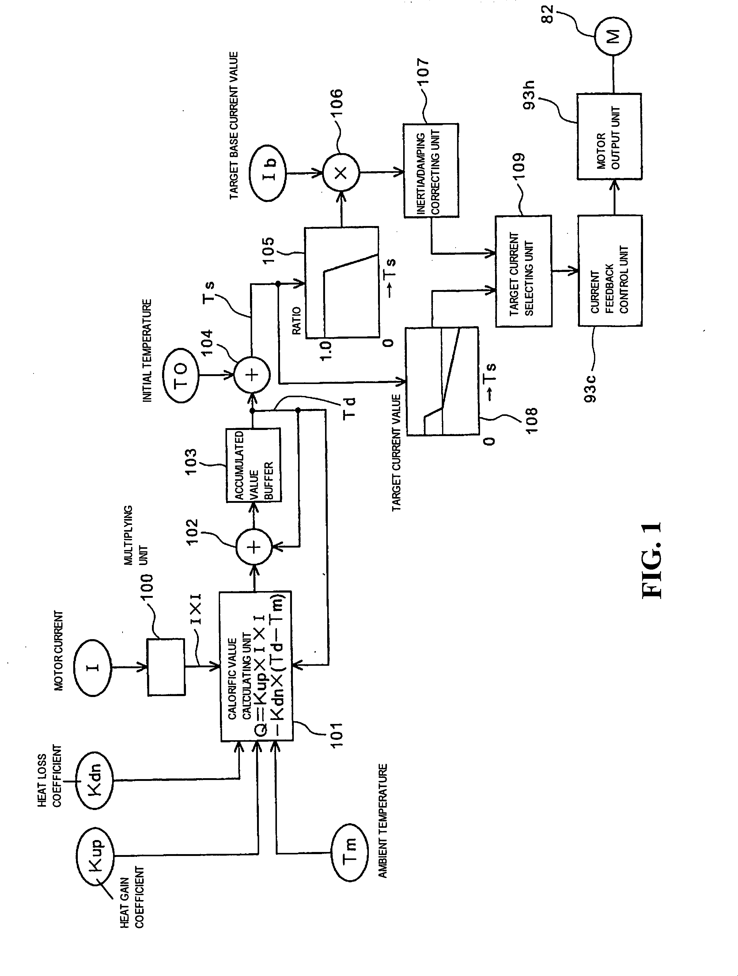
To precisely detect the temperature of a power assist motor without using a temperature sensor and enhance an overheating protection function. A calorific value calculating unit calculates a calorific value based upon the difference between a calorific value by current supplied to a motor and the quantity of heat radiation. The output of the calorific value calculating unit is accumulated and an accumulated value is input to an accumulated value buffer. A cumulative value TS acquired by adding initial temperature T0 to a cumulative value Td is input to a ratio map of a target current value, ratio is read, and a target base current value is limited according to the ratio. The cumulative value TS used in the map is not an actual motor current value and is calculated based upon unlimited current acquired in an unlimited current calculating unit.

Description

CROSS-REFERENCE TO RELATED APPLICATIONS[0001]The present application claims priority under 35 USC 119 to Japanese Patent Application Nos. 2006-203151 filed on Jul. 26, 2006 and 2006-229150 Aug. 25, 2006 the entire contents of which are hereby incorporated by reference.BACKGROUND OF THE INVENTION[0002]1. Field of the Invention[0003]The present invention relates to motor protection systems. More particularly to a motor protection system for protecting a motor used for electric power steering for example by a motor overheating prevention function. In addition, the present invention relates to overheating prevention systems. More particularly, to a system that estimates the temperature of a motor and a motor peripheral device, limits current according to estimated temperature and protects the motor and the motor peripheral device from overheating.[0004]2. Description of Background Art[0005]An electric power steering system is known that applies a turning assist force by an electric moto...

Claims


Application Information

Patent Timeline
IPC IPC(8): B62D5/04B62D6/00H02H7/08
CPCB62D5/04H02H6/00B62D5/0496B62D5/046Y10S388/934
Inventor OGAWA, SUMITAKA
Owner HONDA MOTOR CO LTD
Learn More