Current direction detection circuit and switching regulator having the same

a detection circuit and switching regulator technology, applied in the direction of electric variable regulation, process and machine control, instruments, etc., can solve the problems of power loss, waste of power consumption, noise generation, etc., and achieve the effect of reducing current losses and better suppressing power losses

Inactive Publication Date: 2008-01-31
ROHM CO LTD
View PDF5 Cites 169 Cited by
  • Summary
  • Abstract
  • Description
  • Claims
  • Application Information

AI Technical Summary

Benefits of technology

[0013] In order to overcome the problems described above, preferred embodiments of the present invention provide a current direction detection circuit wherein even better suppression of power losses can be achieved in a switching regulator, for example, and in which a small sized circuit can be provided. Another preferred embodiment of the present invention provides a switching regulator in which current losses can be minimized by such a current direction detection circuit and wherein there is no possibility of reactivation of the current direction detection circuit after detection of a reverse direction current.
[0016] In the current direction detection circuit according to the above-described preferred embodiments of the present invention, due to the configuration of the monitoring transistor, the impedance element, the first and second constant-current sources, the reference transistor, and the sensing transistor, the control signal is output upon detection of the condition just prior to the point where the current flowing in the ground side output transistor starts to flow in the reverse direction. Therefore, it becomes possible to further minimize the power loss thereof when used in a switching regulator, for example, and furthermore the size of the circuitry can be made small. Also, in the switching regulator according to the above-described preferred embodiments of the present invention, the current direction detection circuit cannot be reactivated after detection of the current in the reverse direction, so wasted power consumption produced by ringing or generation of noise can be minimized.

Problems solved by technology

The inventor of the present application, as a result of studies directed at achieving further improvements in power efficiency, discovered that there is a certain delay (period to in FIG. 4) from detection of the reverse direction current of the ground side output transistor 112 by the current direction detection circuit 116, before ground side output transistor 112 is turned off, and this delay allows a reverse direction current to flow for a certain period of time, which therefore results in power loss.
Also, with the switching regulator 101, as shown in FIG. 4, there is a risk that a swing, i.e., ringing of the gradually decaying voltage generated after the forcible turning off of the ground side output transistor 112 will cause the voltage VD at the node D to drop below ground potential, resulting in instantaneous activation of the current direction detection circuit 116, with consequent wasted power consumption or generation of noise.

Method used


Image

  • Current direction detection circuit and switching regulator having the same
  • Current direction detection circuit and switching regulator having the same
  • Current direction detection circuit and switching regulator having the same

Examples


Embodiment Construction

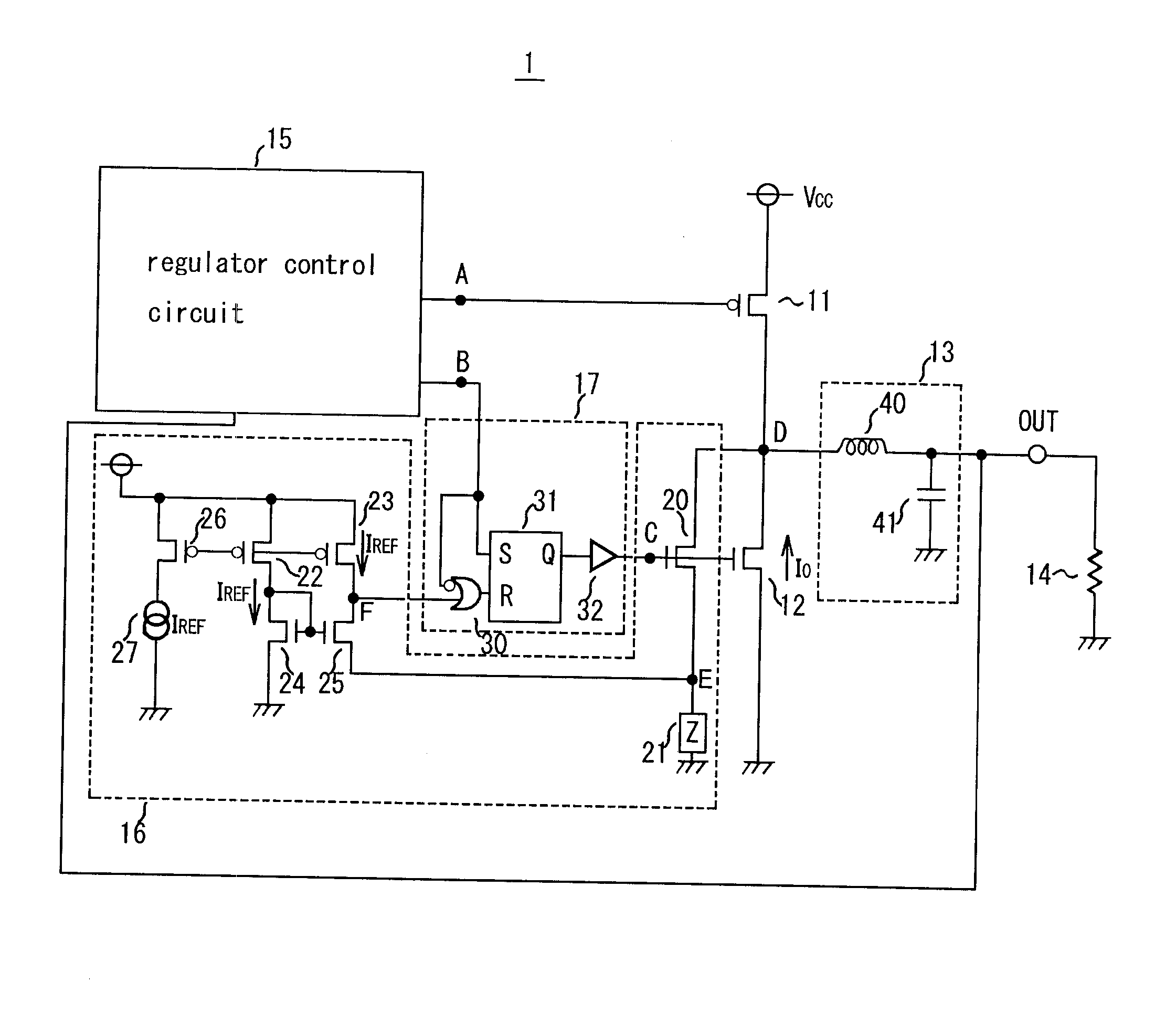
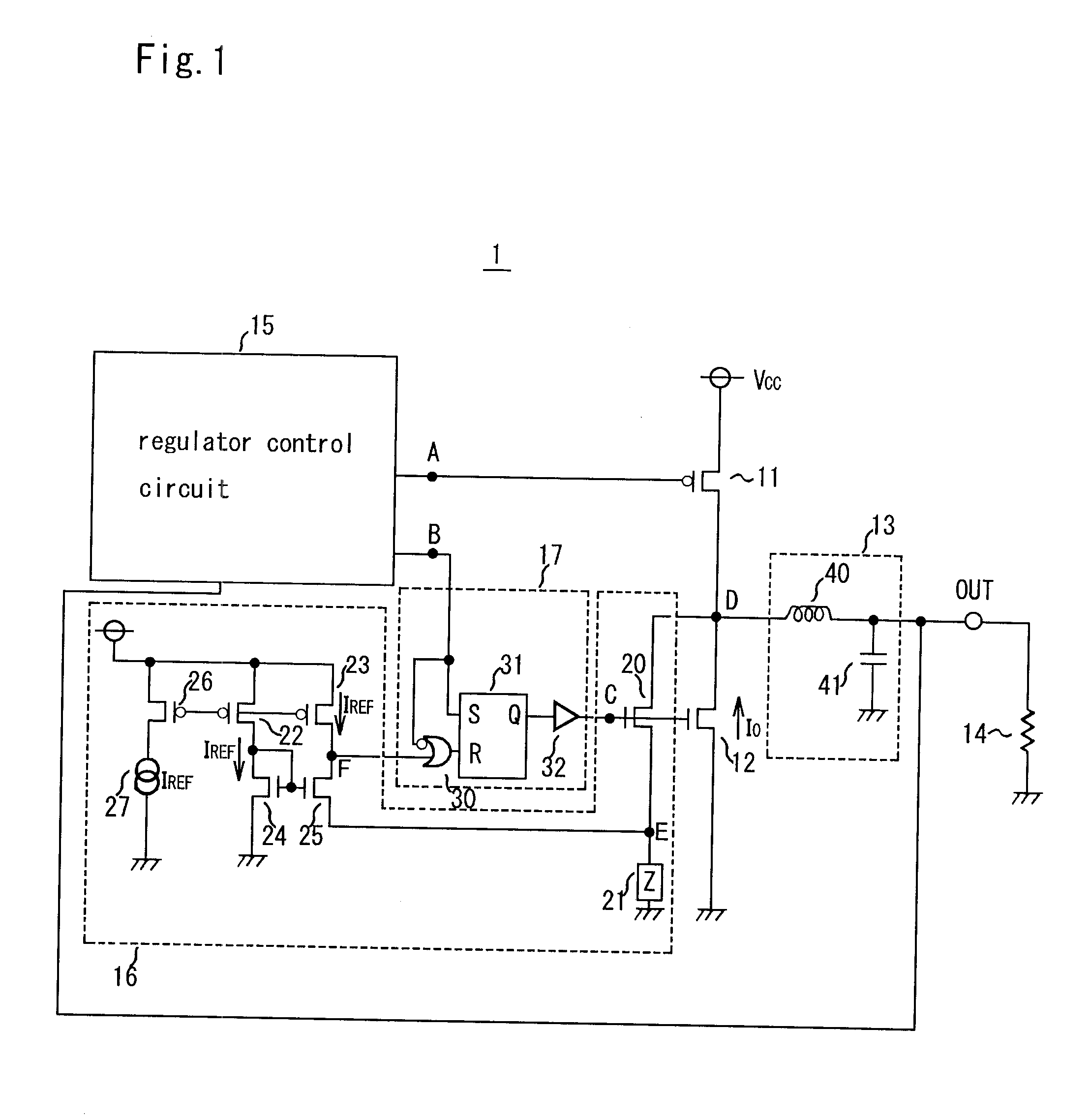
[0022] Preferred embodiments of the present invention are described below with reference to the drawings. FIG. 1 is a circuit diagram of a current direction detection circuit and a switching regulator including the same according to a preferred embodiment of the present invention. The switching regulator 1 includes a power source side output transistor 11 defined by a P type MOS transistor and a ground side output transistor 12 defined by an N type MOS transistor connected in series between the input power source VCC and ground potential; a smoothing circuit 13 having an input terminal connected between the two transistors 11, 12 and an output terminal connected to the output terminal (switching regulator output terminal) OUT; a regulator control circuit 15 that outputs a control signal A and control signal B that perform on / off control of the power source side output transistor 11 and ground side output transistor 12 so as to maintain a predetermined DC voltage by inputting as feed...


PUM


Abstract

A current direction detection circuit includes a monitoring transistor having a control terminal and an output terminal respectively connected with a control terminal and an output terminal of a ground side output transistor; an impedance element having one terminal connected with an input terminal of the monitoring transistor and the other terminal grounded; first and second constant-current sources; a diode-connected reference transistor interposed between the first constant-current source and ground potential; and a sensing transistor interposed between the second constant-current source and the impedance element and having a control terminal connected with the control terminal of the reference transistor. The current direction detection circuit is small yet capable of minimizing power loss of a switching regulator.

Description

BACKGROUND OF THE INVENTION [0001] 1. Field of the Invention [0002] The present invention relates to a current direction detection circuit that, when reverse direction current flows in a ground side output transistor, is capable of detecting the flow of current, and relates to a switching regulator including the current direction detection circuit. [0003] 2. Description of the Related Art [0004] A switching regulator is provided with a power source side output transistor, that defines a main switching element, between a terminal that inputs power and a terminal that is connected with the load and outputs a predetermined DC voltage, and maintains a predetermined DC voltage by turning on / off (conductive / non-conductive) the power source side output transistor. Such regulators are of small size and are capable of achieving high power efficiency and thus are widely used. In recent years, synchronous rectifying switching regulators have been used (see, for example, Japanese Patent Applica...

Claims


Application Information

Patent Timeline
Patent Type & Authority Applications(United States)
IPC IPC(8): G05F1/46G01R27/16H02M3/137H02M3/155H02M3/156H02M3/158H02M7/48
CPCH02M3/156Y02B70/1466H02M2001/0009H02M3/1588H02M1/0009Y02B70/10H02M3/04H02M3/158
Inventor HOJO, YOSHIYUKI
Owner ROHM CO LTD
Why Eureka
Try Eureka