Electrical device and battery pack

a battery pack and electric device technology, applied in the direction of cell components, primary cell maintenance/service, safety/protection circuit, etc., can solve the problems of inconvenient use, drastic temperature rise of the cell, and the inability to charge the secondary battery, so as to prevent polarity reversal and less concern

Inactive Publication Date: 2008-01-31
PANASONIC CORP
View PDF4 Cites 5 Cited by
  • Summary
  • Abstract
  • Description
  • Claims
  • Application Information

AI Technical Summary

Benefits of technology

[0021] The battery in the electrical device and the battery pack in such a configuration is short-circuited by the short circuiting portion when the battery output voltage is lower than a particular preset voltage, and the positive and negative electrodes of the battery are charged to the same voltage, preventing polarity reversal, and thus, there is less concern about the drastic temperature rise and leakage of the battery.

Problems solved by technology

In the tread toward improvement in performance, power consumption of portable electrical devices such as cellphone and digital camera is also increasing gradually.
The main power sources for portable electrical devices are mainly secondary batteries, but such a secondary battery should be charged with a battery charger or with a power supply device called AC adapter that converts commercial AC power supply voltage into DC charging voltage, as it is connected to commercial AC power source, and thus, use of it outdoor, where the secondary battery cannot be charged, is inconvenient.
However, the primary or secondary battery used as main power source and the primary battery used as auxiliary power source in the electrical device described above may be discharged by leak current into an excessive discharge state if they are left connected to the circuit of the electrical device.
These batteries have a problem that they may be degraded, causing leakage and drastic temperature rise of the cell in the excessive discharge state.
Along with progress of discharge of the alkaline battery, the voltage of the manganese electrode declines gradually and the voltage of the zinc electrode rises gradually, leading to decrease in output voltage, and, when the output voltage reaches a discharge terminating voltage, the lowest voltage allowing reliable discharge, the voltage of the zinc electrode rises beyond the hydrogen gas generating voltage, resulting in generation of hydrogen gas from the zinc electrode.
In such a case, after the polarity reversal, the precipitated lithium dendrite penetrates through the separator, causing short circuiting of the lithium electrode with the manganese electrode, and the short-circuit current may raise the temperature of the lithium battery rapidly.
The deposited iron then penetrates through the separator, causing short-circuiting of the lithium electrode with the manganese electrode, and the short-circuit current may raise the temperature of the lithium battery rapidly.
As described above, a battery in the excessive discharge state may cause troubles such as leakage of its solution and rapid temperature rise, and thus, various methods were proposed to solve the problems.
However, as described in Japanese Unexamined Patent Publication No. 2002-525806(kohyo), the battery containing an excessive discharge prohibiting circuit by the method of preventing excessive discharge by using an excessive discharge prohibiting circuit is indeed a high-resistance resistor, but there remained a possibility of a trace amount of current flowing in the battery.
Similarly to the methods described in Japanese Patent Unexamined Publication Nos. 07-272770 and 2004-502280(kohyo), the method of using an absorbent absorbing the hydrogen gas generated in the alkaline battery had a problem that pressure rise and leakage of the battery occur by the unabsorbed hydrogen gas because, if hydrogen gas is generated in an amount more than the hydrogen-absorbing capacity of the hydrogen-adsorbing substance, it is not possible to absorb the hydrogen gas completely.

Method used


Image

  • Electrical device and battery pack
  • Electrical device and battery pack
  • Electrical device and battery pack

Examples


Embodiment Construction

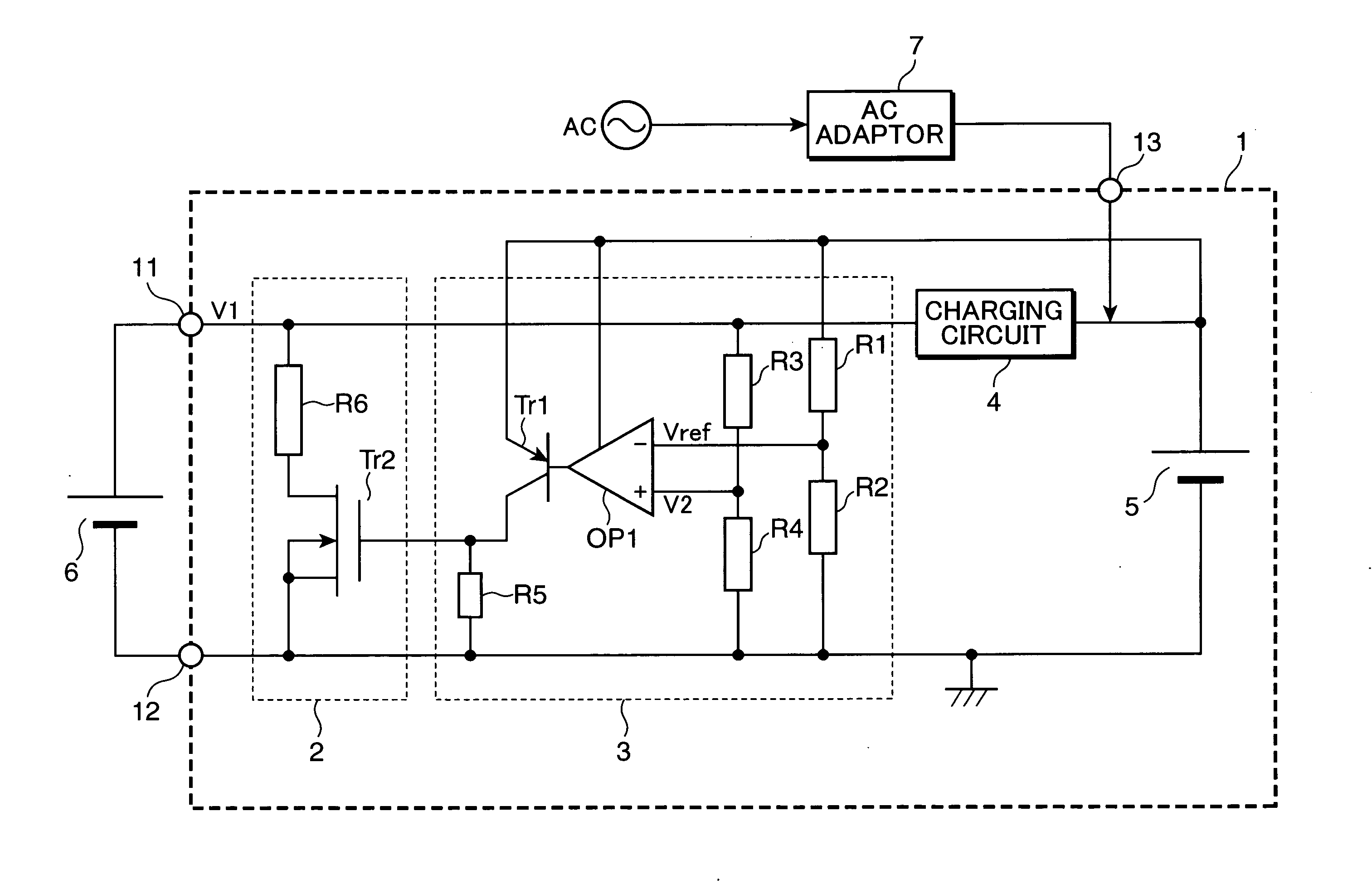
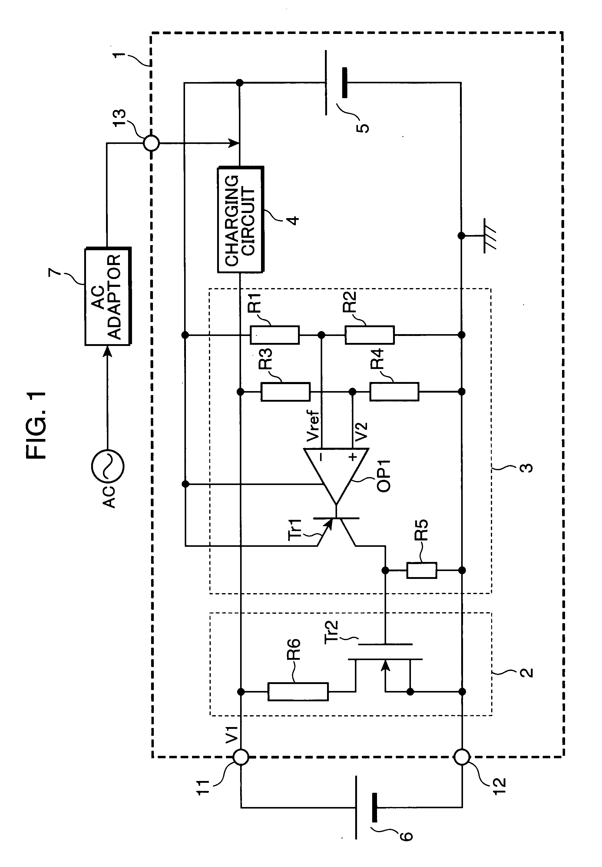
[0030] Hereinafter, favorable embodiments of the present invention will be described with reference to drawings. The codes common in respective Figures indicate the same components, and duplicated description is omitted. FIG. 1 is a block diagram showing an example of the configuration of the electrical device in an embodiment of the present invention. The electrical device 1 shown in FIG. 1 is a portable electrical device such as cellphone or digital camera, using a secondary battery as its power source. The electrical device 1 shown in FIG. 1 has, for example, a positive electrode terminal 11, a negative electrode terminal 12, an external-power-source lead terminal 13, a short circuiting portion 2, a voltage detector 3, a charging circuit 4 (charger), and a secondary battery 5. The electrical device 1 is configured to charge the main power source, secondary battery 5, with output power from an auxiliary power source, primary battery 6 (battery), connected externally to the positiv...


PUM


Abstract

An electrical device comprises a positive electrode terminal for connection to the positive electrode of a battery, a negative electrode terminal for connection to the negative electrode of the battery, a load circuit receiving power from the positive and negative electrode terminals connected to the battery, a voltage detector detecting the voltage between the positive and negative electrode terminals, and a short circuiting portion for short-circuiting between the positive and negative electrode terminals when the voltage detected by the voltage detector becomes not larger than a particular preset voltage.

Description

BACKGROUND OF THE INVENTION [0001] 1. Field of the Invention [0002] The present invention relates to an electrical device using a battery and also to a battery pack. [0003] 2. Description of the Prior Art [0004] Batteries have been used widely as a power source for electrical devices. [0005] Examples of the electrical devices using such a battery as power source include those in the structure having a compartment removably storing a primary battery, those having a chargeable secondary battery in the main body, and the like. [0006] In the tread toward improvement in performance, power consumption of portable electrical devices such as cellphone and digital camera is also increasing gradually. Accordingly, the main power source for such a high-performance portable electrical device is preferably larger in capacity and higher in energy density. The main power sources for portable electrical devices are mainly secondary batteries, but such a secondary battery should be charged with a ba...

Claims


Application Information

Patent Timeline
Patent Type & Authority Applications(United States)
IPC IPC(8): H02H9/04
CPCH01M2/348H01M6/5044H02J7/0054H02J7/0029H01M10/4228H02J7/342Y02E60/10H01M50/581
Inventor TAKAMURA, KOSHIICHINOSE, TOSHIHIKOSHIMAMURA, HARUNARI
Owner PANASONIC CORP
Why Eureka
Try Eureka