

Air-cooled hydrogen fuel cell system and emission control method
A fuel cell system and fuel cell technology, applied in the direction of fuel cells, fuel cell additives, fuel cell heat exchange, etc., can solve problems such as inability to warn of abnormal conditions, inability to eliminate the risk of water accumulation in the flow field, and inability to adjust discharge strategies, etc. , to achieve the effect of eliminating the risk of water accumulation, optimizing the control strategy, and preventing the phenomenon of reverse polarity
- Summary
- Abstract
- Description
- Claims
- Application Information
AI Technical Summary
Problems solved by technology
Method used
Image

Examples
Embodiment 1
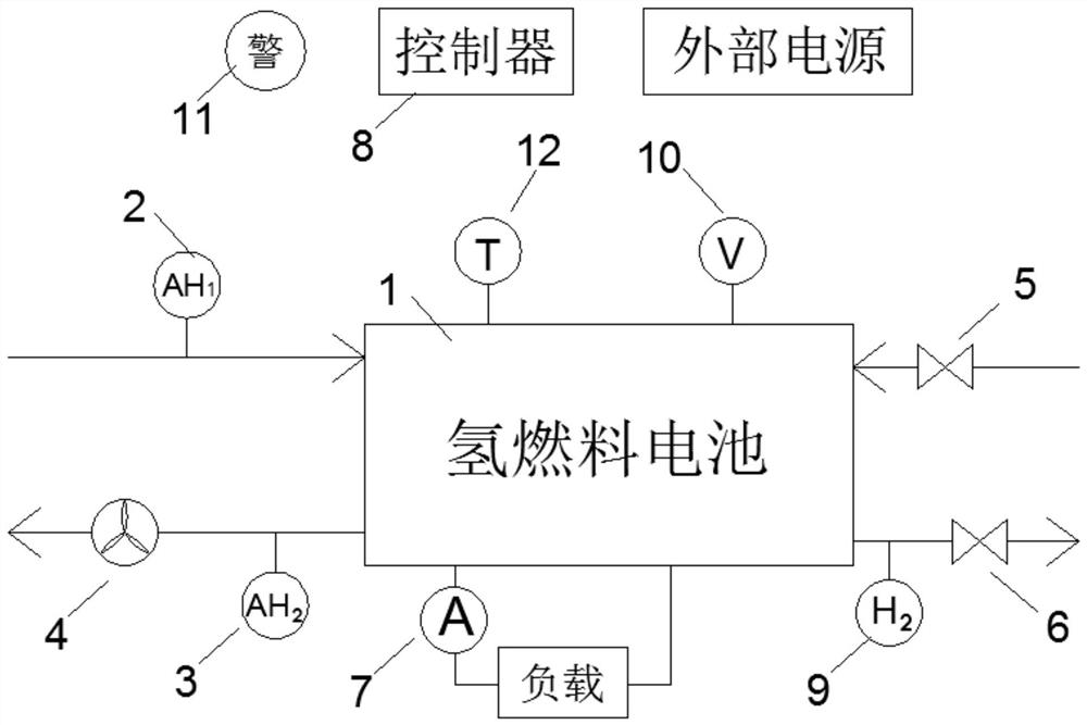
[0043] see attached figure 1 . An air-cooled hydrogen fuel cell system, comprising a hydrogen fuel cell 1, a first humidity sensor 2, a second humidity sensor 3, an exhaust fan 4, an intake solenoid valve 5, an exhaust solenoid valve 6, a current meter 7 and a controller 8 The hydrogen fuel cell 1 generates electricity through the electrochemical reaction between the hydrogen supplied to the anode side of the hydrogen fuel cell 1 and the oxygen in the air at the cathode side of the hydrogen fuel cell 1; the first humidity sensor 2 is used to obtain the information entering the hydrogen fuel cell 1. The absolute humidity of the air on the cathode side; the second humidity sensor 3 is used to obtain the absolute humidity of the air discharged from the cathode side of the hydrogen fuel cell 1; the exhaust fan 4 is used to provide air to flow on the cathode side of the hydrogen fuel cell 1 The power of the gas inlet solenoid valve 5 is used to control the entry of hydrogen into t...
Embodiment 2
[0045] see attached figure 1. An air-cooled hydrogen fuel cell system, comprising a hydrogen fuel cell 1, a first humidity sensor 2, a second humidity sensor 3, an exhaust fan 4, an intake solenoid valve 5, an exhaust solenoid valve 6, a current meter 7 and a controller 8 The hydrogen fuel cell 1 generates electricity through the electrochemical reaction between the hydrogen supplied to the anode side of the hydrogen fuel cell 1 and the oxygen in the air at the cathode side of the hydrogen fuel cell 1; the first humidity sensor 2 is used to obtain the information entering the hydrogen fuel cell 1. The absolute humidity of the air on the cathode side; the second humidity sensor 3 is used to obtain the absolute humidity of the air discharged from the cathode side of the hydrogen fuel cell 1; the exhaust fan 4 is used to provide air to flow on the cathode side of the hydrogen fuel cell 1 The power of the gas inlet solenoid valve 5 is used to control the entry of hydrogen into th...
Embodiment 3
[0051] see attached figure 1 . An air-cooled hydrogen fuel cell system, comprising a hydrogen fuel cell 1, a first humidity sensor 2, a second humidity sensor 3, an exhaust fan 4, an intake solenoid valve 5, an exhaust solenoid valve 6, a current meter 7 and a controller 8 The hydrogen fuel cell 1 generates electricity through the electrochemical reaction between the hydrogen supplied to the anode side of the hydrogen fuel cell 1 and the oxygen in the air at the cathode side of the hydrogen fuel cell 1; the first humidity sensor 2 is used to obtain the information entering the hydrogen fuel cell 1. The absolute humidity of the air on the cathode side; the second humidity sensor 3 is used to obtain the absolute humidity of the air discharged from the cathode side of the hydrogen fuel cell 1; the exhaust fan 4 is used to provide air to flow on the cathode side of the hydrogen fuel cell 1 The power of the gas inlet solenoid valve 5 is used to control the entry of hydrogen into t...
PUM
 Abstract
Description
Claims
Application Information