System and method for controlling communication in a multi-network environment

a multi-network environment and communication control technology, applied in the field of communication networks, can solve the problems of inability to control communication in multi-network environment, so as to achieve efficient communication pathways

Inactive Publication Date: 2008-01-31
AVAGO TECH WIRELESS IP SINGAPORE PTE
View PDF10 Cites 30 Cited by
  • Summary
  • Abstract
  • Description
  • Claims
  • Application Information

AI Technical Summary

Benefits of technology

[0024] The present invention solves many of the foregoing problems in a variety of embodiments. The network of the present invention has a plurality of computing devices at least one of which is a mobile terminal device configured with a wireless transceiver. The network comprises a plurality of access devices arranged in a spanning tree configuration to support communications among the plurality of computing devices, and at least one of the plurality of access devices is configured to selectively intercept, store and forward requested data, thereby reducing traffic on the communication network. Further, at least one of the plurality of access devices may be configured to selectively intercept and store requested processing resources for future processing, again reducing traffic on the communication network. The processing resources stored may be, for example, those that perform the function of decoding signals representative of two-dimensional images captured by a two-dimensional code reading device. In addition, at least one of said plurality of access devices may be configured to selectively intercept, store and forward requested program code, once again reducing traffic on the communication network.
[0027] In another embodiment, a communication network of the present invention has a mobile terminal device configured with a wireless transceiver. The communication network also comprises a data source and a plurality of access devices. The plurality of access devices are arranged to provide a communication pathway between the mobile terminal device and the computing device. Moreover, at least one of said plurality of access devices is configured to monitor communication traffic through that access devices, and to selectively store for future forwarding requested data so as to shorten the communication pathway from the data to the mobile terminal device.

Problems solved by technology

However, multiple radio base station networks have their own inherent problems.
For example, in a multiple base station network employing a single shared channel, each base station transmission is prone to collision with neighboring base station transmissions in the overlapping coverage areas between the base stations.
Therefore, it often proves undesirable for each base station to use a single or common communication channel.
Again, however, changing operating parameters between coverage areas creates difficulties for the roaming devices which move therebetween.
In particular, when different communication parameters are used, a portable or mobile device roaming into a new base station coverage area is not able to communicate with the new base station without obtaining and synchronizing to the new parameters.
This causes communication backlog in the network.
Such configurations, however, do not always provide for efficient communication.
While permitting such transmissions, wide area networks (WANs) only provide point-to-point communications, use a narrow bandwidth, and often exhibit heavy communication traffic.
Moreover, WANs require relatively higher transmission power—a negative factor in the ever increasing need for power savings associated with portable transceiving devices.
As a result, WANs are generally slow and expensive, and simply do not provide an effective overall solution.
As a result, portable computer terminals have been effectively disabled from independently performing many needed tasks.
Others have been stretched to a nearly unacceptable limit of portability, battery life and processing and storage ability.
However, the mobile terminal is still required to use the relatively expensive and delayed services provided by the WAN for each such request, which often prove unacceptable for a given task.

Method used


Image

  • System and method for controlling communication in a multi-network environment
  • System and method for controlling communication in a multi-network environment
  • System and method for controlling communication in a multi-network environment

Examples


Embodiment Construction

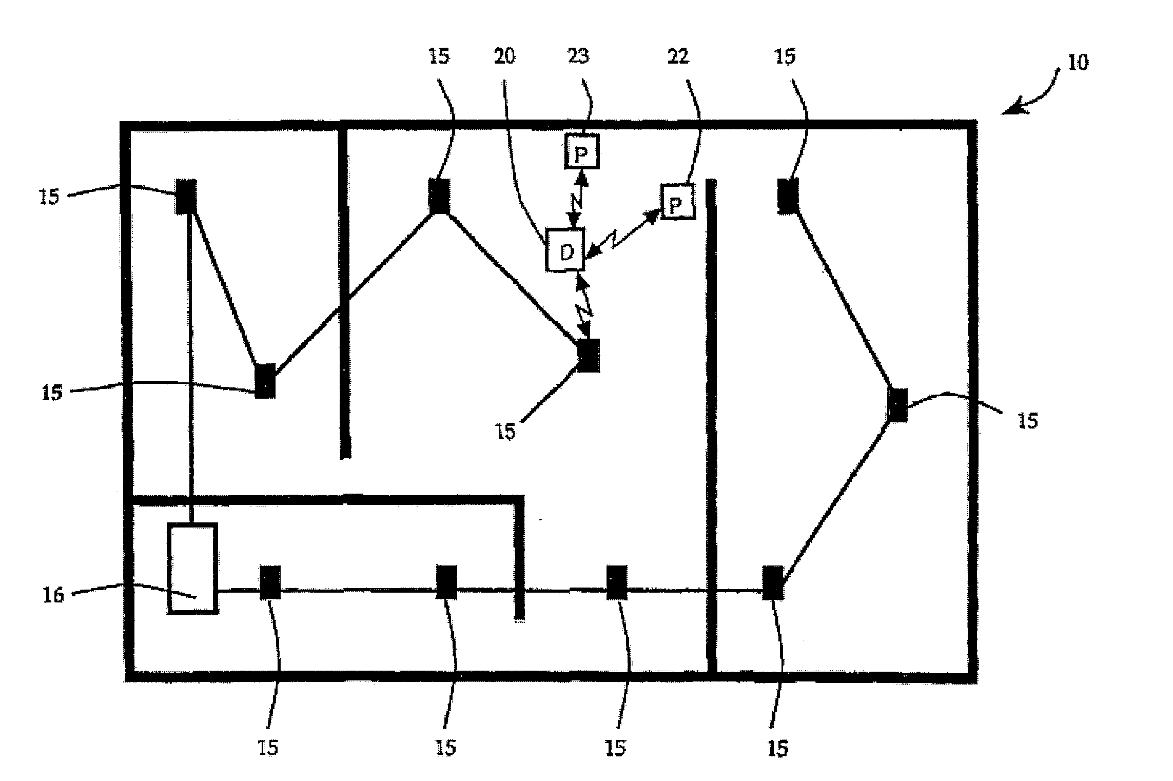
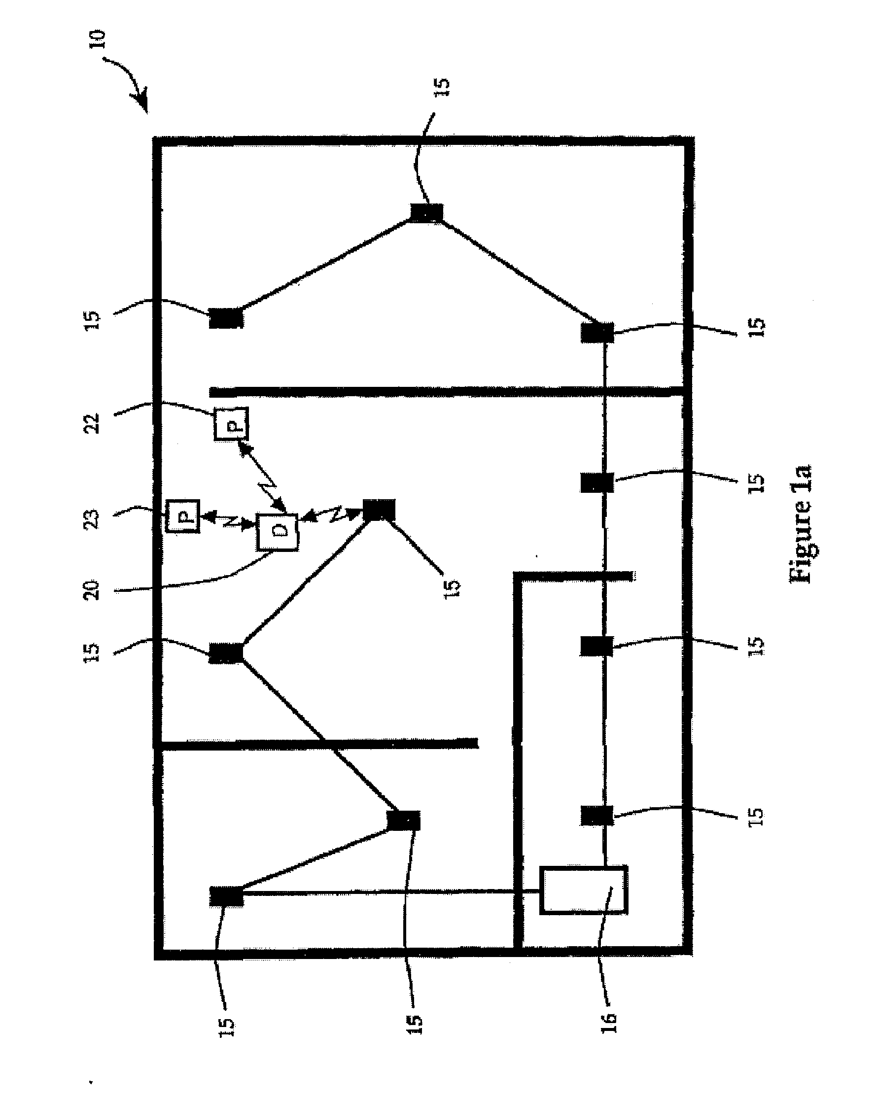
[0097]FIG. 1A illustrates a hierarchical communication system 10 within a building in accordance with the present invention. The illustrated hierarchical communication system 10 includes a local area network (LAN) for maintaining typical communication flow within the building premises, herein referred to as a premises LAN. The premises LAN is designed to provide efficient end-to-end routing of information among hardwired and wireless, stationary and roaming devices located within the hierarchical communication system 10.

[0098] The premises LAN consists of an infrastructure network comprising radio base stations, i.e., wireless access points 15, and a data base server 16 which may be part of a more extensive, wired LAN (not shown). Herein, base stations which participate in routing and relaying data throughout the communication network are referred to as “access points.” If they also participate in the storage or migration of data and program code or in local processing, the base st...


PUM


Abstract

A hierarchical communication system, arranged in a spanning tree configuration, is described in which wired and wireless communication networks exhibiting substantially different characteristics are employed in an overall scheme to link portable or mobile computing devices. Copies of data, program code and processing resources are migrated from their source toward requesting destinations based on request frequency, communication link costs and available local storage and / or processing resources. Each appropriately configured network device acts as an active participant in network migration. In addition, portable two-dimensional (2-D) code reading terminals are configured to wirelessly communicate compressed 2-D images toward stationary access servers that identify the code image through decoding and through comparison with a database of images that have previously been decoded and stored.

Description

CROSS REFERENCE TO RELATED APPLICATIONS Claiming Benefit Under 35 U.S.C. 120 [0001] This application is a continuation in part of U.S. Application Serial Numbers: a) Ser. No. 08 / 279,148, filed Jul. 22, 1994 (Attorney Docket Nos. 10082US11; DN37998XD); b) Ser. No. 07 / 876,629, filed Apr. 30, 1992 (Attorney Docket Nos. 92P275; DN36837D); and c) Ser. No. 08 / 267,758, filed Jul. 5, 1994 (Attorney Docket Nos. 10554US02; DN37613A). [0002] The application U.S. Ser. No. 08 / 279,148 is a continuation-in-part of: PCT Application Serial No. PCT / US94 / 05037 filed May 6, 1994 (Attorney Docket Nos. 10082WO08; DN37998XAX); U.S. application Ser. No. 08 / 205,639 filed Mar. 4, 1994 (Attorney Docket Nos. DN37139XXA; 10458US03); and U.S. application Ser. No. 08 / 275,821, filed Jun. 10, 1994 (Attorney Docket Nos. 10082US10; DN37998XC). [0003] PCT Application Serial No. PCT / US94 / 05037 is based on U.S. application Ser. No. 08 / 198,404, filed Feb. 22, 1994 (Attorney Docket Nos. 10082US07; DN37998XA), which is its...

Claims


Application Information

Patent Timeline
Patent Type & Authority Applications(United States)
IPC IPC(8): H04L12/28H04B7/005H04L1/00H04L1/16H04L29/12H04M7/00H04W52/46
CPCH04L1/0002H04L1/0025H04L1/0032H04L1/0038H04W52/46H04L1/1685H04L29/12009H04L61/00H04M7/006H04L1/1671
Inventor MAHANY, RONALD L.WEST, GUY J.BUNTE, ALAN G.DANIELSON, ARVIN D.MORRIS, MICHAEL D.MEIER, ROBERT C.
Owner AVAGO TECH WIRELESS IP SINGAPORE PTE
Why Eureka
Try Eureka