
Image Processing Device

a technology of image processing and image, which is applied in the field of image processing devices, can solve the problems of difficult to alter a task, and complicated control and altering the task scheduling table, and achieve the effect of convenient execution

Active Publication Date: 2008-01-31
HITACHI ASTEMO LTD
View PDF1 Cites 16 Cited by
  • Summary
  • Abstract
  • Description
  • Claims
  • Application Information

AI Technical Summary

Benefits of technology

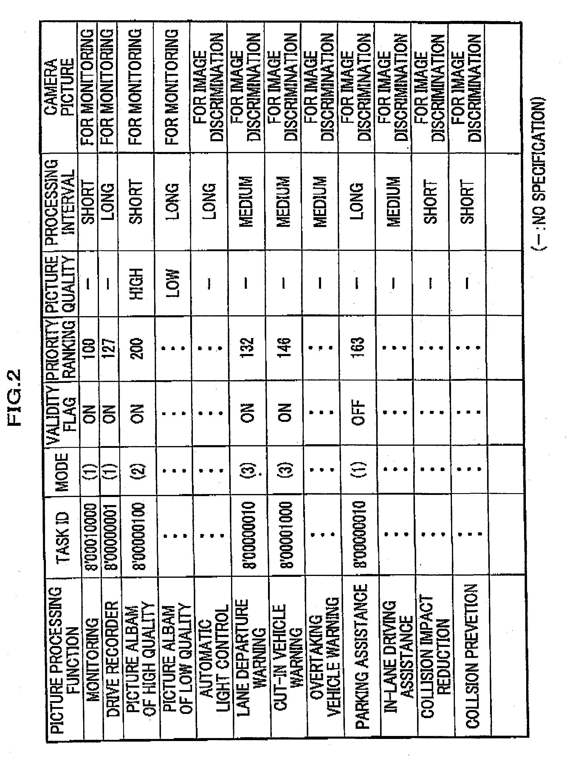
[0006] An image processing device to detect an environment around a running vehicle has to implement image processing functions in accordance with vehicle's running velocity and the movement of an object to be measured. For instance, when the vehicle is running at a high speed, the processing interval has to be made so short that a driver in the vehicle does not lose sight of the object to be measured. When an image processing function used for a safe system is implemented, a processing needs to be performed reiteratively for a short period to enhance reliability of the resultant image to be obtained depending on the circumstance. In such a case it is necessary to alter the schedule for each task to be performed as often as the task alteration and the circumstance require. On the other hand, if the task scheduling control method, which is disclosed in Japanese Laid-open Patent Application No. 06-67899 and Japanese Laid-open Patent Application No. 2000-299841, it is difficult to alter a task because all the tasks registered in the task scheduling table have to be taken into account. For instance, supposing that the timing for a certain function to be performed is to be altered, this alteration has to be made after checking every function on its performance status, that is, how it is being performed. However since it is difficult to check every function on its performance status, altering the task is not easy. Moreover it is necessary to take it into account that a task scheduling table has to be made based on a task that is performed at the longest interval. Accordingly if a task can be scheduled to be performed at a longer interval, other tasks have to be scheduled to be performed based on the longest task interval and it is rather complicated to control and alter the task scheduling table. As mentioned above, there is a problem that altering the task scheduling can not be done when a function is exchanged or a task performance interval is altered unless every function is checked on its performance status.
[0007] The objective of the present invention is to facilitate control over tasks to realize each function. In other words, the objective of the present invention is to facilitate altering the performance interval of each task when it needs to be altered to adjust to a new circumstance deleting a currently implemented function and adding a new function.
[0009] According to the present invention, the task management of the image processing functions is easily performed while a plurality of image processing fixations are working. To be specific, changing the processing interval of each task and adding and deleting functions in accordance with the change in the peripheral circumstance, which is an object image processing functions deal with, are easily executed. Moreover each task is independently controlled with this invention and it is possible to download dynamically a program, upgrade each function program independently while the execution program varies depending on the function and alter an operation to change a function.

Problems solved by technology

On the other hand, if the task scheduling control method, which is disclosed in Japanese Laid-open Patent Application No. 06-67899 and Japanese Laid-open Patent Application No. 2000-299841, it is difficult to alter a task because all the tasks registered in the task scheduling table have to be taken into account.
However since it is difficult to check every function on its performance status, altering the task is not easy.
Accordingly if a task can be scheduled to be performed at a longer interval, other tasks have to be scheduled to be performed based on the longest task interval and it is rather complicated to control and alter the task scheduling table.
As mentioned above, there is a problem that altering the task scheduling can not be done when a function is exchanged or a task performance interval is altered unless every function is checked on its performance status.

Method used


Image

  • Image Processing Device
  • Image Processing Device
  • Image Processing Device

Examples


Embodiment Construction

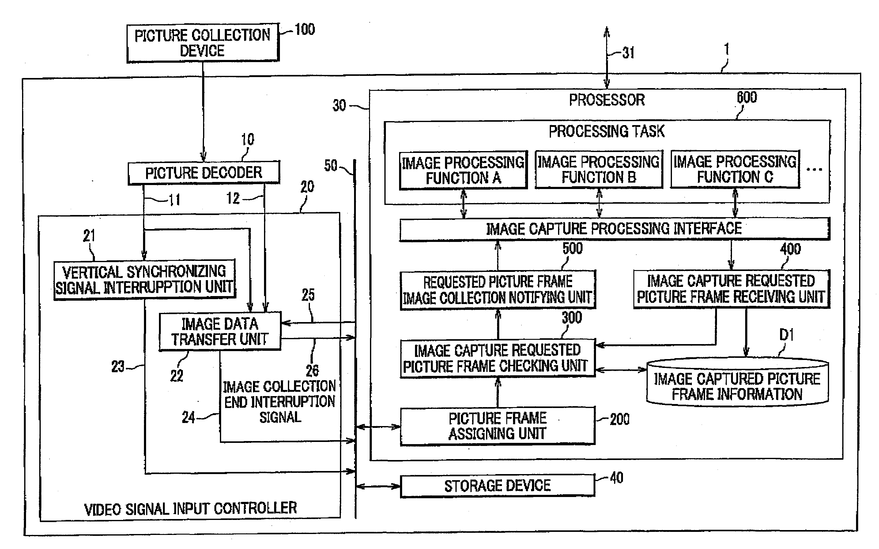
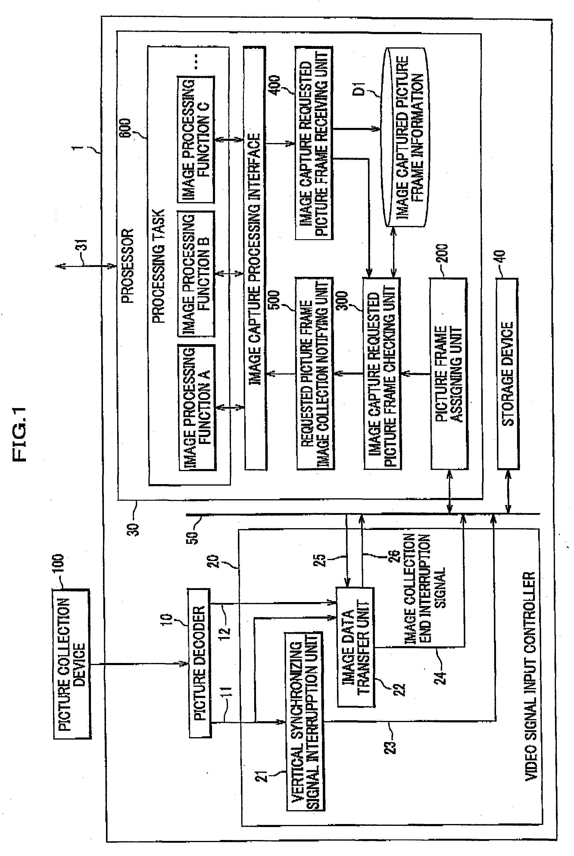
[0028] Looking to the figures attached, the embodiments of the present invention is explained in detail. To begin with, an explanation is given on the configuration of an embodiment of the present invention. The image processing device 1 includes a video decoder 10, a video signal input unit 20, a processor 30 and a storage device 40. From a picture collection part 100 that consists of such devices as a video camera, an image pick-up device and a hard disk recorder, picture data 110 are input to the video decoder 10. The video signal 110 that is input are divided through the video decoder 10 into synchronizing signals 11 and image data 12. If the video signal contains analog information, the video decoder 10 is an equivalent to a device called video-reorder and capable of performing both analog-digital transformation and separation of synchronizing signals. Both the vertical synchronizing signal 11 and the picture signal 12 are transmitted to the video signal input controller 20. Th...


PUM


Abstract

An image processing device of the present invention performs a task to execute an image processing This image processing device comprises a picture frame assigning unit that assigns an identification number to the image data to be collected by a picture collection device, an image capture requested picture of checking unit that checks whether the image data to which the identification number is assigned is identical with the image data that is requested by the task, an requested picture frame image collection notification unit that notifies the task of the image data having been collected which the task requests, if the image data to which the picture frame number is assigned is identical with the image data which the task requests, and an image capture requested picture frame receiving unit receives an image collection request from the task.

Description

CROSS REFERENCE TO RELATED APPLICATION [0001] This application claims the foreign priority benefit under Title 35, United States Code, § 119(a)-(c), of Japanese Patent Application No. 2006-198876, filed on Jul. 21, 2006 with the Japanese Patent Office, the disclosure of which is herein incorporated by reference in its entirety. BACKGROUND OF THE INVENTION [0002] This invention relates to a image processing device to implement a plurality of image processing functions simultaneously, especially relates to task scheduling of the plurality of image processing functions. [0003] As both computer technology and picture technology have been drastically developed in recent years, it has become import to realize an image processing device to implement a plurality of image processing functions simultaneously. For instance, one image processing device with a camera which is installed on a automobile vehicle is requested to be capable of both discriminating a road lane and detecting an obstacle...

Claims


Application Information

Patent Timeline
Patent Type & Authority Applications(United States)
IPC IPC(8): G06K9/62
CPCH04N5/772H04N21/4223H04N5/782
Inventor MURAMATSU, SHOJINAKAMIKAWA, TSTSUAKISHIMA, TAKESHIOTSUKA, YUJIHIGUCHI, MIRAIMONJI, TATSUHIKOIRIE, KOTA
Owner HITACHI ASTEMO LTD
Learn More