
System and method for creating cheap efficient high-speed home networks.

a high-speed home network, cheap technology, applied in the direction of digital transmission, telephonic communication, electromagnetic transmission, etc., can solve the problem of less efficient course, and achieve the effect of avoiding bandwidth collisions with neighboring apartments and less sa

Inactive Publication Date: 2008-01-31
MAYER YARON +1
View PDF11 Cites 30 Cited by
  • Summary
  • Abstract
  • Description
  • Claims
  • Application Information

AI Technical Summary

Benefits of technology

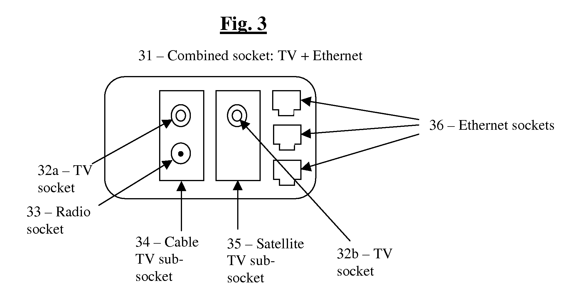
[0010] If the users want for example to be able to use at least one mobile computer in the house, then preferably they can plug into one or more of the end sockets for example a device which translates the Ethernet communication for example to wireless communication, however this is preferably done by optic wireless communications (for example by using infrared), or for example by using UWB, which is typically limited to a few meters range, since this is much safer in terms of being protected from outside espionage and avoiding bandwidth collisions with neighboring apartments, and this way preferably each wireless outlet preferably covers more or less only the room in which it is installed.
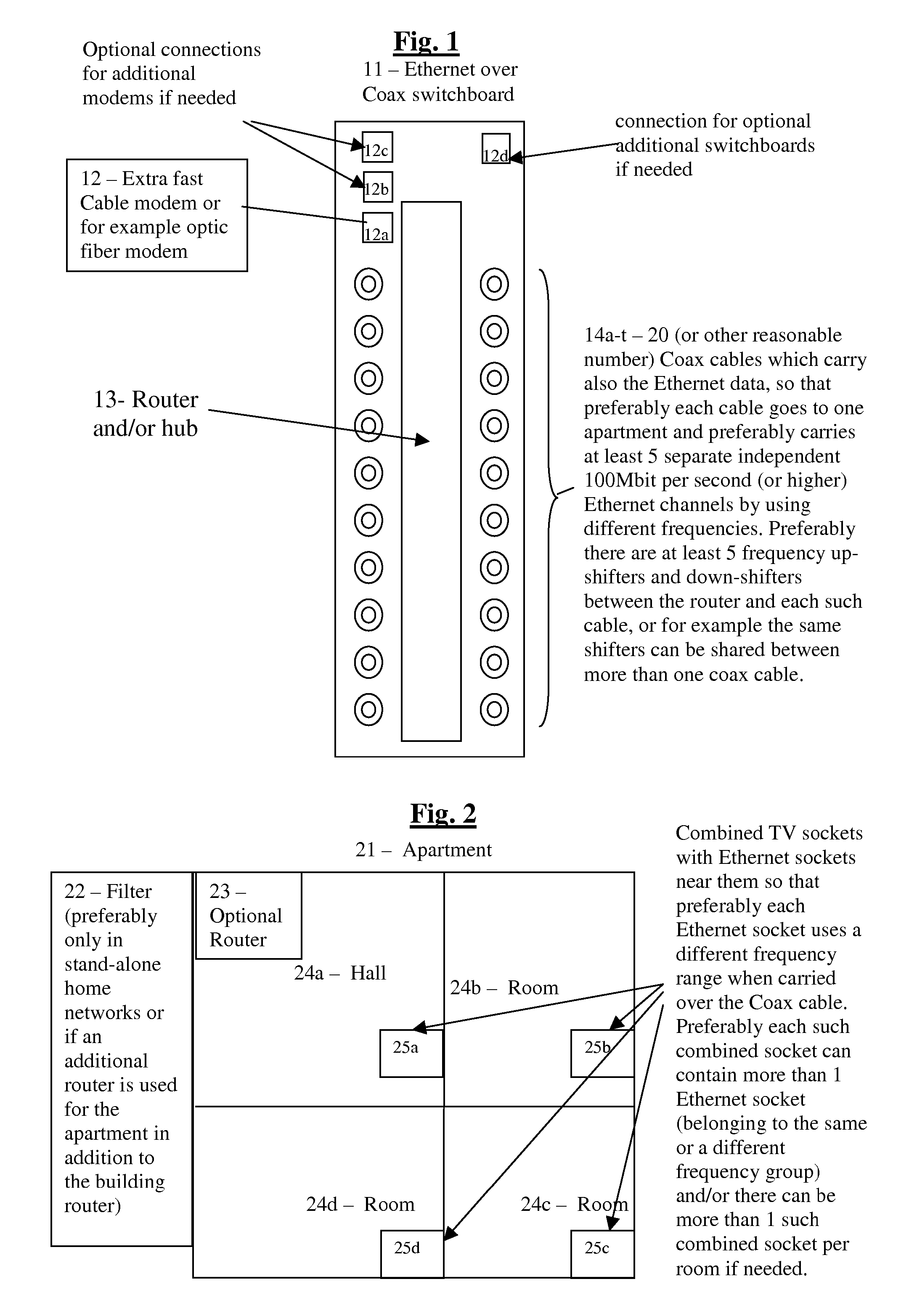
[0011] In addition, if the standalone home network variation is used (i.e. without the shared building router and modem) then preferably a filter (or filters) is added, preferably at the point where the coax cable enters the apartment, which preferably prevents the DC current and the frequencies of above the normal cable TV broadcasts (typically above 860 MHz) from going outside the apartment. If the integrated building solution is used, then preferably such filters are added between the system at the bottom of the building and the coax cable that enters the building—to prevents the DC current and the frequencies of above the normal cable TV broadcasts from going outside the building. Another possible variation is to add the additional router in the apartment even in the integrated building solution, so that packets communicating between computers within the apartment don't leave the apartment, since letting internal communications go through the building's routers exposes the user to security risks for example in case someone taps into the lines in the stairway or into the shared routers of the building. In this case preferably the filter of signals above the Cable TV broadcasts is also added at the apartment preferably between the apartment and the rest of the building (preferably at the entrance to the apartment), so that preferably only the router of the apartment can enable packets of data on the network to move in or out of the apartment, and so preferably on both sides of this router separate up-shifters and down-shifters are used for each side of the coax cable (outside the apartment and inside of it). Another possible variation is that for example data encryption is preferably automatically added for example (preferably by the communications software on each of the communicating computers) when computers in the apartments communicate which each other, so that the shared building router can also be used for this communication without the need to add the additional router inside the apartment, eventhough it is still less safe than preventing altogether access to the data outside the apartment. This is preferably done by the user defining for example the IP addresses (and / or for example preferably some other hardware identifying codes) of the computers which are considered to be part of the internal apartment network, so that the relevant communication software on each of these computers knows which communications to encrypt and decrypt automatically, and / or for example the shared building router can automatically send this info to the computers in each apartment (for example according to the coax cable that goes into it, so that the user does not have to feed this information manually for example when installing the network), but this is less safe since it means that a hacker tempering with the shared building router might send misleading information to the computers in the apartment about the other computers in the internal apartment network, thus causing the encryption to be removed.
[0013] Preferably the shared building router or routers can also be programmed from afar for example by the ISP, so that preferably users can preferably dynamically preferably instantly change internet definitions preferably without any need for hardware configuration changes in the apartment or in the building, so that for example the users in some apartment can dynamically change for example the sharing relations (i.e. for example the configuration and / or the ratios) between the computers in the apartment for example from a single Internet connection shared by 3 computers in the apartment for example to 2 Internet connections, one alone and one shared by 2 computers or to 3 separate connections, or vice versa—converting separate connections into a single shared connection, and / or for example dynamically change the uplink and / or downlink definitions of each Internet connection. So for example for changing these sharing relations and / or the uplink and / or downlink of each defined connection preferably the relevant multi-apartment router simply changes definitions of how much up and down bandwidth is available for each logical connection and how much is shared between which computers in the relevant apartment, and preferably enforces it for example by treating packets to or from these sharing computers (except for example packets of direct communication between these computers) like packets that go to or from the same IP address for bandwidth limitation purposes (eventhough each of the computers sharing the same Internet connection has a separate IP address). Another possible variation is that for example for changing the sharing relations between computers within the same apartment the users can directly for example change the relevant parameters in the building router without having to make this change through the ISP (for example by a special software which the ISP provides them). (If a separate router is used at the apartment then preferably the sharing relations between the computers in the apartment are controlled by this router and then of course the user can preferably change these sharing relations without needing to contact the ISP). Another possible variation is that preferably such shared connections can also preferably be created or removed for example across separate apartments, however that implementation could be much less desired both by the ISP (since it can mean reduced payments) and by users (since it means depending on the neighbors without knowing how they really intend to use the Internet, so that the users might actually get much less bandwidth than what they expect if for example the neighbor is going to occupy most of the bandwidth most of the time). Another possible variation is that these shared routers of the buildings can also be used for example for communicating directly for example with the electricity meters and / or water meters of apartments (for example by using smart meters which communicate for example through TCP / IP or other methods), and so preferably for example the electricity company or the water authorities can use remote readings instead of having to send someone once in a while to read the meters manually.

Problems solved by technology

Another possible variation for example in separate independent home networks is for example to use only one frequency, but that is of course less efficient since the bandwidth of for example 100 Mbps becomes shared between the various computers (which is especially problematic if some computers also share data between themselves), unless for example each room (or at least some of the rooms) preferably has a separate coax cable so that for example the coax cables of different rooms all connect to the central hub or router for example at the entrance to the apartment, thus forming for example the shape of a root or tree.

Method used


Image

  • System and method for creating cheap efficient high-speed home networks.
  • System and method for creating cheap efficient high-speed home networks.
  • System and method for creating cheap efficient high-speed home networks.

Examples


Embodiment Construction

[0024] All of the descriptions in this and other sections are intended to be illustrative examples and not limiting.

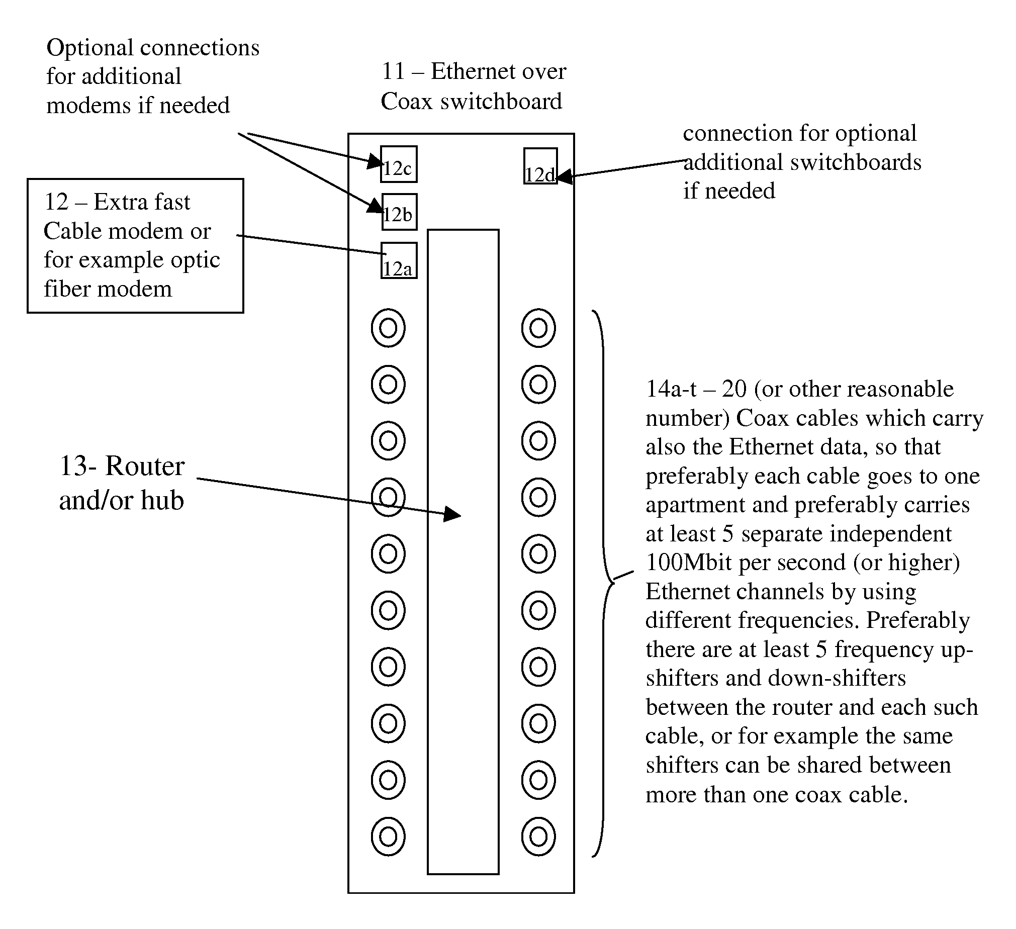
[0025] Referring to FIG. 1, we show an illustration of a typical configuration of one or more shared building units (11), each unit preferably connecting multiple apartments, with preferably at least one coax cable (14) for each apartment (in this example there are 20 such coax cables, marked 14a-t, but of course this can be also any other reasonable number), so that preferably for example at least 5 separate Ethernet frequencies are preferably used over the same coax cable preferably for each apartment. Preferably there are for example at least 5 frequency up-shifters and down-shifters between the router and / or hub (13) and each such cable, or for example the same shifters can be shared between more than one coax cables. The shared unit or switchboard (11) preferably connects (for example through connectors 12a-c) to the Internet for example with 1 or more extra fast...


PUM


Abstract

Broadband connections of end users to the Internet are becoming more and more common today, and the most common types of these fast connections are ADSL and Cable modems. These connections are typically still very slow compared to the speeds that are expected in the next few years and typically also highly asymmetric and allow typically 750-2000 Kbit per second (most typically 1500 Kbit) for the downlink and typically for example 96 Kbit or 128 Kbit per second for the uplink (although standard ADSL can in principle support up to 8 Mbit per second download speed and up to 800 Kbit per second upload speed), based on the assumption that most users download much more data than they upload. However, for many users these limitations are highly undesirable, and these are for example home users or small businesses or organizations who want to use the connection also for example for VOIP (voice over IP) communications and / or Video-over IP communications and / or conferences and / or for example running web servers and / or for example various p2p applications, and in fact the low uplink also many times slows down the downlink due to the overhead needed for dealing with relatively small packets, so that any additional uplink by the user can severely limit the real downlink that can be achieved below the downlink bandwidth which the user is paying for. Actually ADSL is beginning to be replaced in some places by VDSL where the distance to the nearest street switchboard is about 1.2 Kilometers or less, which in principle allows up to 52 Mbit per second Download speed and up to 16 Mbit per Second Upload speed. However, these modems are expensive and are only slowly entering the market and only in a few countries. On the other hand there is no need to upgrade typical cable modems for enabling faster speeds, such as for example 20 Mbit downlink and 2 Mbit uplink, as is offered for example in France, when the ISPs start offering such speeds—since the typical common cable modem is already capable of such speeds. The present invention enables an improved Ethernet-over-coax solution which enables using one or a few very high speed modems, each for multiple users or apartments, preferably in combination with very cheap and very fast home networks (offering preferably at least up to 100 Mbit per second for each computer, preferably at full duplex), preferably based on the Cable TV coax cables, so that multiple computers can share the same internet connection for example in the same apartment and / or communicate between themselves. This preferably includes using a different frequency for the Ethernet-over coax channel for each computer in the apartment. Also shown are for example improved home networks using the second set of normally unused 2 phone wires and for example some improvement in HPNA networks, such as for example using HPNA also to connect between the street switchboard and the home or office instead of having to use also for example an ADSL or VDSL modem.

Description

[0001] This patent application claims priority from British application 0607828.1 of Apr. 21, 2006 and from British application 0625693.7 of Dec. 27, 2006, hereby incorporated by reference in their entireties. BACKGROUND OF THE INVENTION [0002] 1. Field of the Invention [0003] The present invention relates to creating cheap efficient high-speed home networks, and more specifically to an improved Ethernet-over-coax solution which enables using one or a few very high speed modems each for multiple users or apartments, preferably in combination with very cheap and very fast home networks, preferably based on the Cable TV coax cables, and preferably with a different frequency over the coax for the Ethernet communications of each end socket in the apartment or at least each computer. [0004] 2. Background [0005] Broadband connections of end users to the Internet are becoming more and more common today, and the most common types of these fast connections are ADSL and Cable modems. These co...

Claims


Application Information

Patent Timeline
IPC IPC(8): H04J14/00H04B10/20
CPCH04M11/062H04L12/2838
Inventor MAYER, YARONGADASSI, HAIM
Owner MAYER YARON
Learn More