Fairing for marine drilling risers

a technology for fairings and risers, applied in the direction of drilling pipes, pipe laying and repair, mechanical equipment, etc., can solve the problems of increasing the danger of equipment failure, now being encountered, and partly successful

Inactive Publication Date: 2008-01-31
CUMING CORP
View PDF6 Cites 38 Cited by
  • Summary
  • Abstract
  • Description
  • Claims
  • Application Information

AI Technical Summary

Benefits of technology

[0005]A fairing includes two half-shells of fiber reinforced plastic or fiberglass. The shell halves are shaped to close around the buoyancy modules (e.g., cylindrical syntactic foam buoyancy modules) commonly used on deep-water risers, but with an extended trailing edge. The fairing includes a tail that streamlines the riser and reduces/prevents formation of the vortex, which causes drag and vibration. Hinges at the tail join the halves and enable them to be opened for assembly around the riser pipe as

Problems solved by technology

As offshore oil and gas exploration moves into deeper and more inhospitable waters, the danger of equipment failure increases.
One of the hazards now being encountered is that of high-speed (e.g., 3 knots and greater) currents damaging the riser pipe that connects a floating drill

Method used


Image

  • Fairing for marine drilling risers
  • Fairing for marine drilling risers
  • Fairing for marine drilling risers

Examples


Embodiment Construction

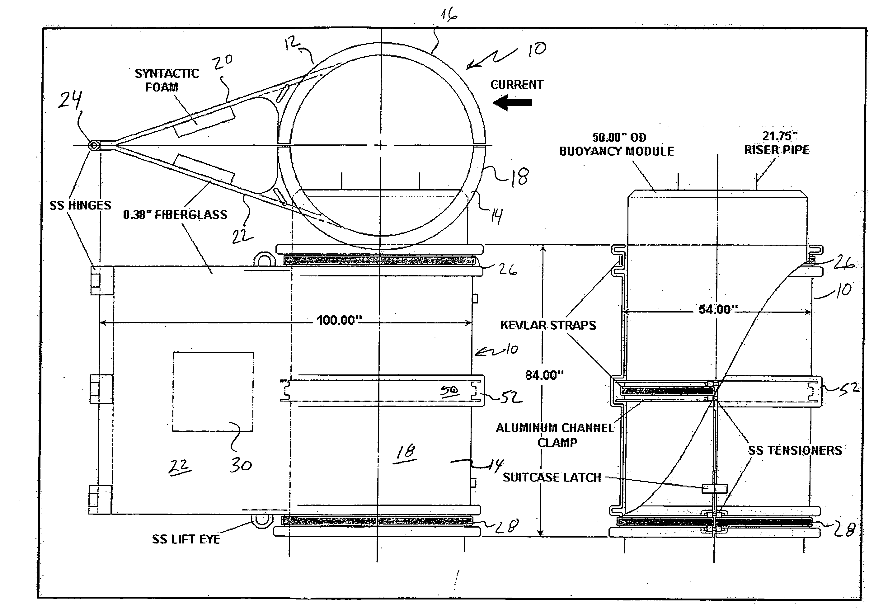
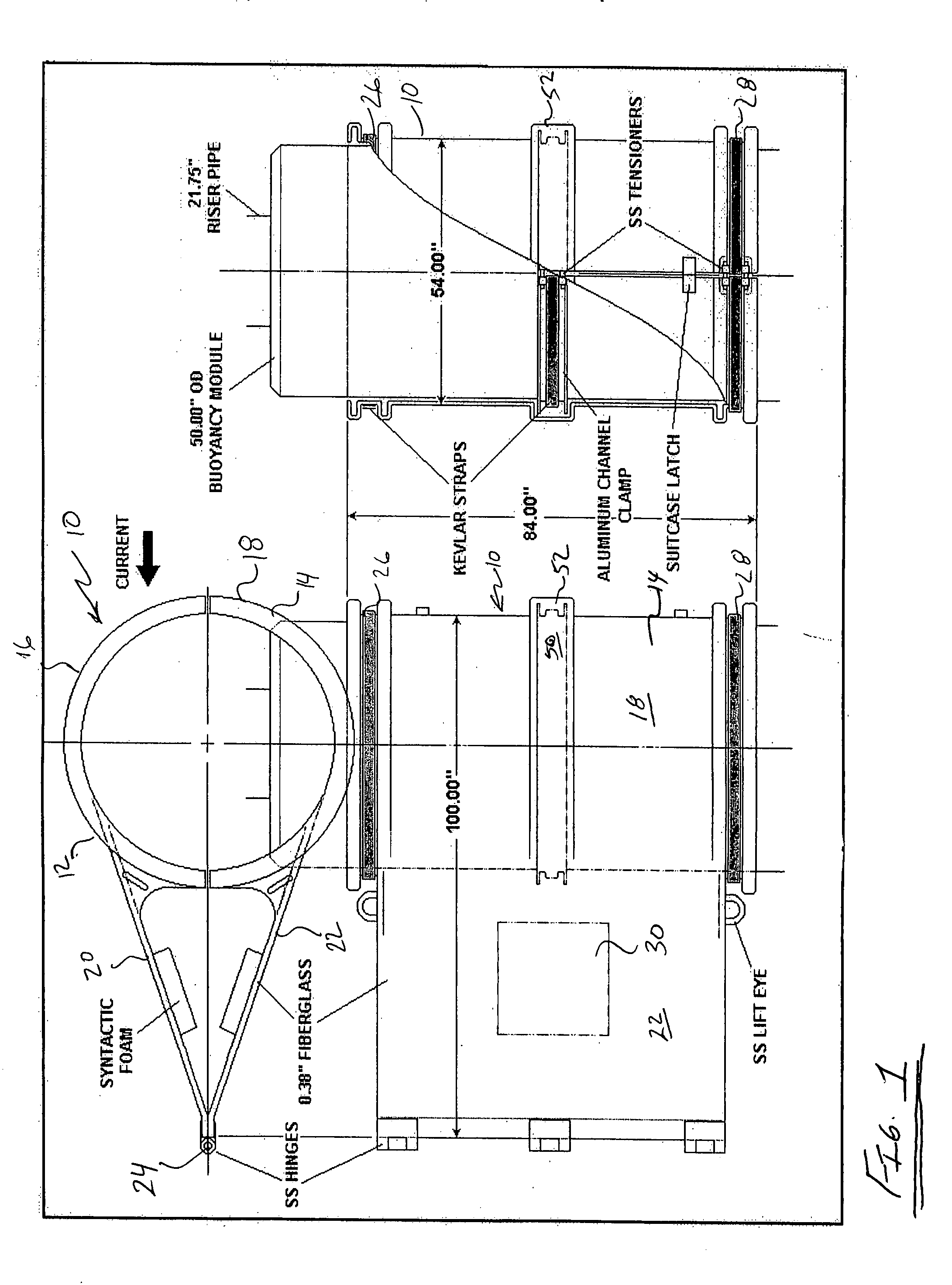
[0013]FIG. 1 illustrates a top view and several side views of a fairing 10. The fairing 10 includes first and second fairing halves 12, 14 that are hinged and operatively secured together. The first and second fairing halves 12, 14 are preferably constructed of fiberglass. The first fairing half 12 includes a first sidewall 16 (e.g., semi-circular), while the second fairing half 14 includes a second sidewall 18 (e.g., semi-circular). The first and second fairing halves 12, 14 include first and second tails 20, 22 respectively, which extend from their associated fairing half and are joined together at a hinge 24.

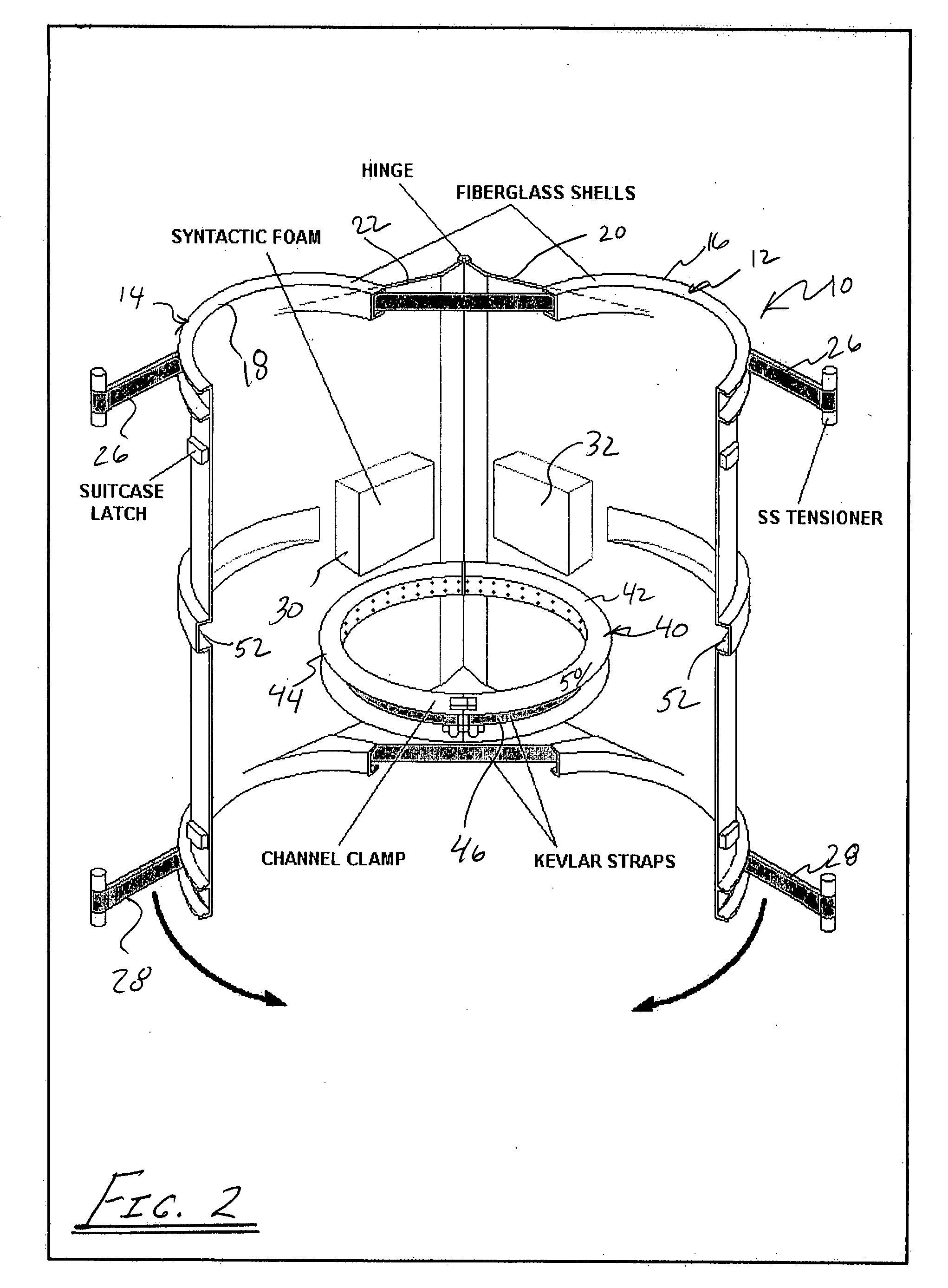
[0014]FIG. 2 illustrates a perspective view of the fairing 10 in the open position. The fairing also includes first and second synthetic straps 26, 28, such as for example KEVLAR straps that are used with associated stainless steel tensioners and suitcase latches to securely close the fairing in an operable position around the buoyancy module. Strong and flexible straps of ar...


PUM


Abstract

A fairing includes two half-shells of fiber reinforced plastic or fiberglass. The shell halves are shaped to close around the buoyancy modules (e.g., cylindrical syntactic foam buoyancy modules) commonly used on deep-water risers, but with an extended trailing edge. The fairing includes a tail that streamlines the riser and reduces/prevents formation of the vortex, which causes drag and vibration. Hinges at the tail join the halves and enable them to be opened for assembly around the riser pipe as it is being run into the water. The fairing may be fastened together by bolted stainless steel tensioners that tightly draw together straps of high strength aramid fiber, such as KEVLAR®. The fairing is positioned on the riser such that the fairing is free to swivel and rotate into the current, while integral buoyancy blocks support the tail. To prevent movement up or down the riser string, the fairing is held in place by a channel clamp gripping the outside diameter of the syntactic foam buoyancy module.

Description

PRIORITY INFORMATION[0001]This application claims priority under 35 U.S.C. §119(e) from U.S. provisional application Ser. No. 60 / 834,219 filed Jul. 28, 2006, which is hereby incorporated by reference.BACKGROUND OF THE INVENTION[0002]As offshore oil and gas exploration moves into deeper and more inhospitable waters, the danger of equipment failure increases. One of the hazards now being encountered is that of high-speed (e.g., 3 knots and greater) currents damaging the riser pipe that connects a floating drill rig to its wellhead on the ocean floor. Such currents exert a massive drag force on the pipe while causing it to shake violently in a phenomenon called vortex-induced vibration (VIV).[0003]Fairings, strakes, shrouds, and similar devices have been used for many years in an attempt to prevent riser damage by currents. These devices have been only partly successful because they were (1) overly complex and expensive; (2) difficult and time-consuming to assemble on board the rig; an...

Claims


Application Information

Patent Timeline
IPC IPC(8): E02D29/00
CPCB63B21/502E21B17/01B63B2021/504F16L1/123
Inventor WATKINS, LOU
Owner CUMING CORP
Why Eureka
Try Eureka