Tool Holder with Vibration Damping Means and a Method for Manufacturing the Same

a technology of vibration damping and tool holders, which is applied in the direction of boring bars, auxiliary equipment, manufacturing tools, etc., can solve the problems of affecting the work process, causing noise when in use, and affecting the use of tool holders in manufacturing machines

Active Publication Date: 2008-01-31
MIRCONA
View PDF41 Cites 6 Cited by
  • Summary
  • Abstract
  • Description
  • Claims
  • Application Information

AI Technical Summary

Benefits of technology

[0011] It is particularly advantageous if the metal or the alloy is applied to the tool holder in the form of a surface covering with a thickness of between 1 μm and 100 μm.
[0012] It is an advantage if the surface covering comprises at least two layers.

Problems solved by technology

Tool holders in manufacturing machines have a tendency to vibrate and give rise to noise when in use.
Such vibration disturbs the work process by having a negative effect on the accuracy of the result.
The vibrations also give rise to a troublesome disturbing noise that worsens the environment around the manufacturing machine.
In practice, vibrations always arise when the various parts of the machine work against each other.
This means that new types of vibration can arise during different periods of the lifetime of the machine.
The vibrations can lead to poor surface finish of the work piece, further wear on the machine and on tools, with, in the worst case, irreparable damage as a consequence.
During the processing of metal materials, problems also arise that are caused by the high level of noise caused by vibrations from the processing and the noise of the machine.
These solutions in general involve troublesome dimensioning procedures and testing procedures before the correct material and properties are found, even if this is possible at all.

Method used


Image

  • Tool Holder with Vibration Damping Means and a Method for Manufacturing the Same
  • Tool Holder with Vibration Damping Means and a Method for Manufacturing the Same

Examples


first embodiment

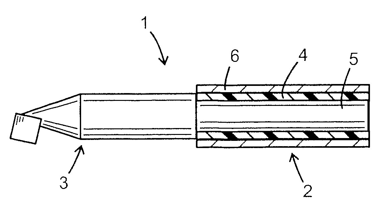
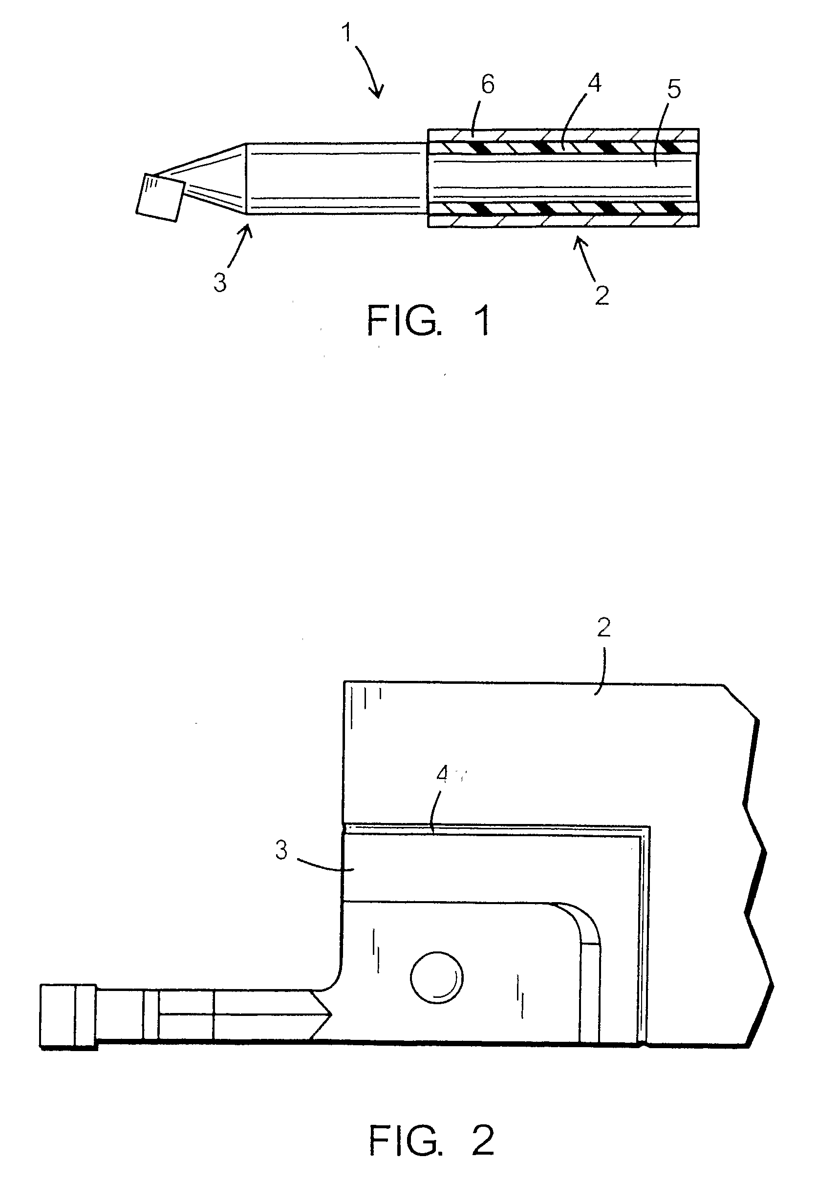
[0018] With reference to FIG. 1, the invention is constituted by a tool holder 1, consisting of a shaft 2 and a head 3. A cutter is intended to be arranged on the head 3. The shaft 2 of the tool holder 1 is provided with a vibration-damping material 4 around its surface 5. A non-compulsory iron tube 6 is arranged around the viscoelastic material 4 intended to distribute more evenly the mounting forces when the tool holder 1 is attached to a manufacturing machine.

second embodiment

[0019] With reference now to FIG. 2, the invention is constituted by a tool holder 1. The tool holder 1 is physically divided into two parts, a forward head 3 intended to accommodate a cutter, and a rear shaft 2 intended to be mounted into a manufacturing machine. The shaft 2 and the head 3 are separated from each other by a vibration-damping material 4. The vibration-damping material 4 may be arranged at any location on the tool holder between the attachment of the cutter into the front end of the tool holder and the region intended for mounting into the manufacturing machine. It is preferable that the vibration-damping material 4 is arranged at the front end in the manner that is shown in FIG. 2.

[0020] The shaft 2 of the tool holder 1 is provided with a vibration-damping material in the form of a metal covering surface on the surface of the tool holder as shown in FIG. 1 or between the shaft 2 and the head 3 as shown in FIG. 2. Thus the vibration-damping material is a metal or an ...


PUM

PropertyMeasurementUnit
thicknessaaaaaaaaaa
thicknessaaaaaaaaaa
vibration-dampingaaaaaaaaaa

Abstract

A tool holder 1 has a shaft 2 intended to be arranged in a tool holder in a manufacturing machine, a head 3 on which a cutter is intended to be arranged and a vibration-damping material 4 arranged between, and attached to, the shaft 2 and the head 3 such that the cutter is in contact with the manufacturing machine solely through the vibration-damping material 4, where the vibration-damping material is a metal or an alloy of metals selected from the group consisting of Cu, Ti, Zn, Al and Ni. A method for manufacturing a tool holder in which the surface covering of vibration-damping material is created by electrochemical pulse plating through the tool holder, when functioning as an electrode, being lowered into an electrolyte containing ions of at least one metal selected from the group consisting of Cu, Ti, Zn, Al and Ni.

Description

BACKGROUND TO THE INVENTION [0001] Tool holders in manufacturing machines have a tendency to vibrate and give rise to noise when in use. Such vibration disturbs the work process by having a negative effect on the accuracy of the result. The vibrations also give rise to a troublesome disturbing noise that worsens the environment around the manufacturing machine. [0002] A perfect manufacturing machine does not give rise to any vibrations, and all energy is passed to the process that is to be carried out. In practice, vibrations always arise when the various parts of the machine work against each other. As the machine becomes more and more worn, changes in its dynamic properties take place. This means that new types of vibration can arise during different periods of the lifetime of the machine. The vibrations can lead to poor surface finish of the work piece, further wear on the machine and on tools, with, in the worst case, irreparable damage as a consequence. [0003] During the proces...

Claims


Application Information

Patent Timeline
Patent Type & Authority Applications(United States)
IPC IPC(8): B23B47/00B23BB23B29/00B23B29/02B23B31/02C25D5/10C25D5/14C25D5/18C25D7/00
CPCB23B29/00B23B31/02B23B2222/56B23B2228/10B23B2250/16B23B2270/54Y10T29/49C25D5/14C25D5/18C25D7/00Y10T408/76Y10T82/2595Y10T409/304312C25D5/10B23B27/002B23B29/02
Inventor MIHIC, PETER
Owner MIRCONA
Why Eureka
Try Eureka