Fuel Cell Module

Active Publication Date: 2008-01-31
TOYOTA JIDOSHA KK
View PDF5 Cites 15 Cited by
  • Summary
  • Abstract
  • Description
  • Claims
  • Application Information

AI Technical Summary

Benefits of technology

[0024] The above gas exhaustion assisting structure preferably includes a slope provided at a junction section between a bottom surface and a side surface of the stepped section for connecting the bottom surface and the side surface. Such a configuration can eliminate a corner which would otherwise be formed by the bottom surface and the side surface contacting each other directly.
[0027] The present invention contributes to a greater suppression of problems caused by a gas bubble.

Problems solved by technology

Such a gap may lead to insufficient adhesion between the separators.
By thus bonding the separators while the gas bubble remains may lead to the following problems caused by the gas bubble 28.
The expanded gas bubble 28 deteriorates adhesiveness of the adhesive 22, and may also partially break the adhesive and lead to gas leakage.

Method used


Image

  • Fuel Cell Module
  • Fuel Cell Module
  • Fuel Cell Module

Examples


Embodiment Construction

[0052] Embodiments of the present invention will now be described with reference to the drawings. Note that the embodiments are merely examples for implementing the present invention, and do not limit the invention.

[Fuel Cell]

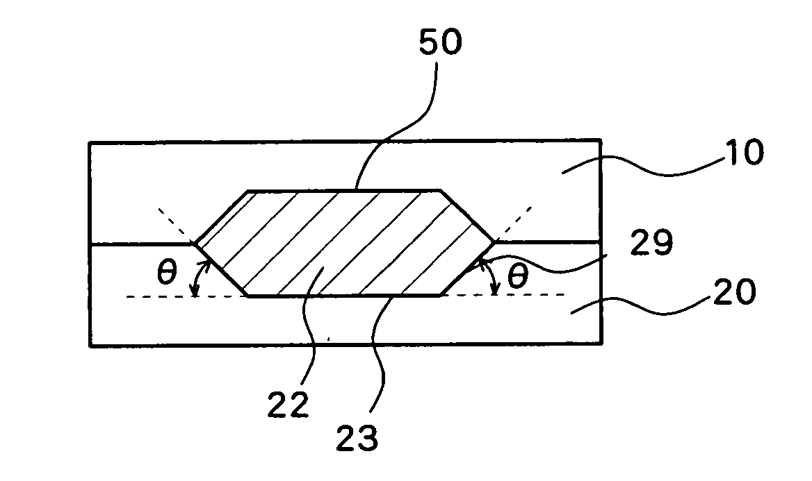
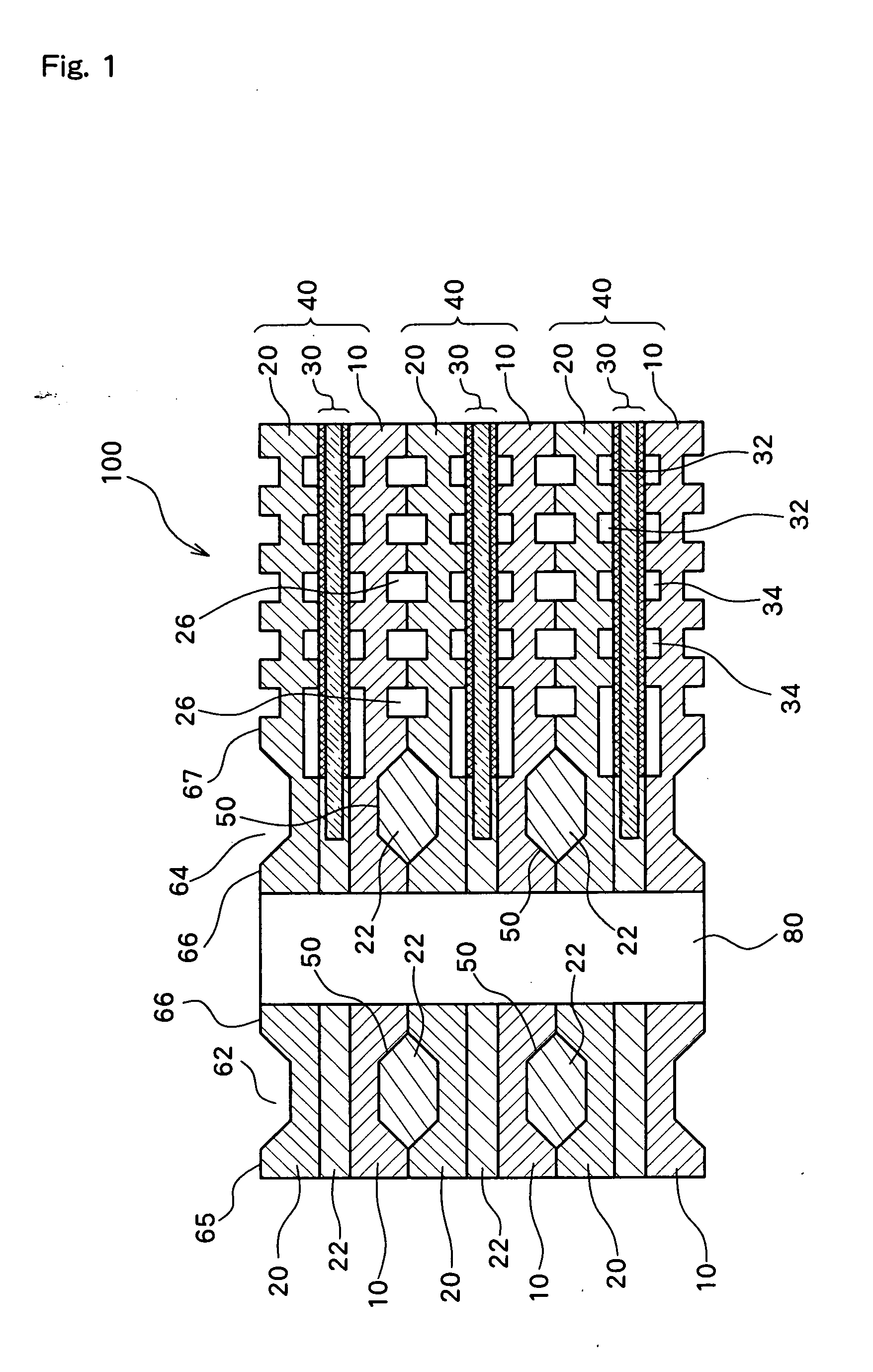
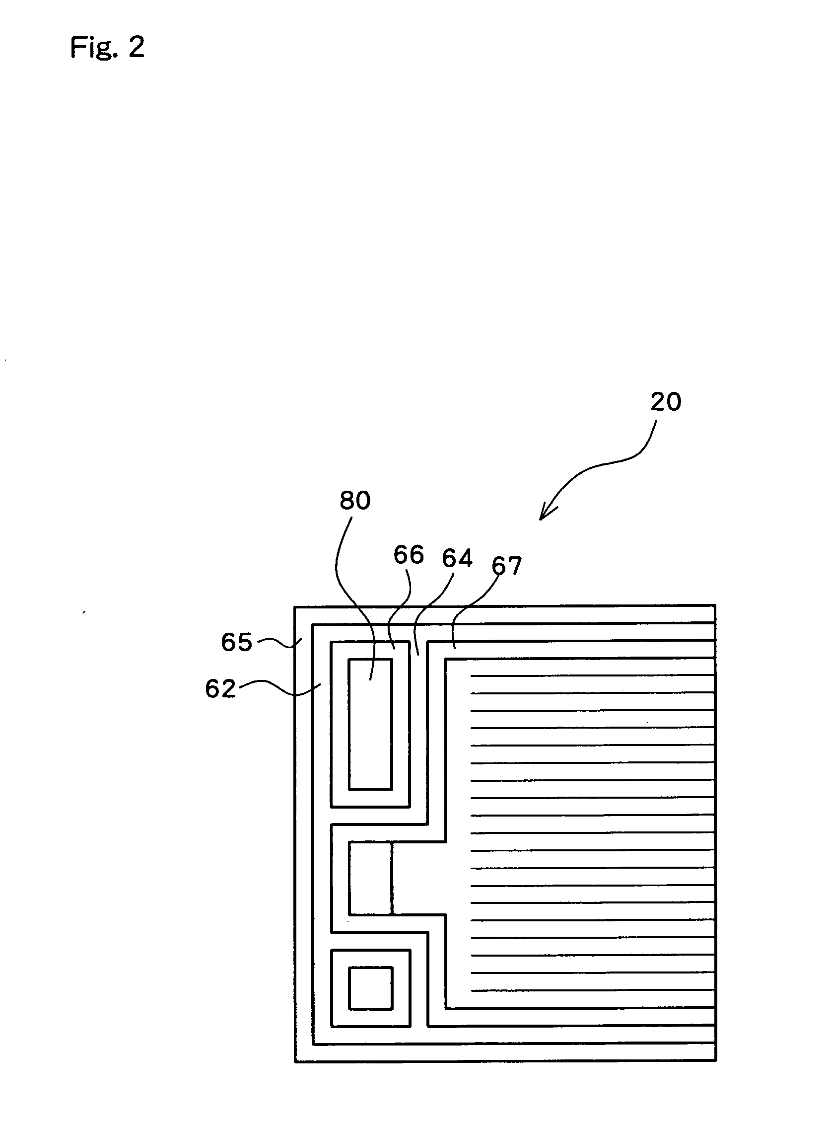
[0053]FIG. 1 discloses a cross sectional view of a fuel cell 100 according to an embodiment of the present invention. FIG. 2 is a plan view of a single separator 20 stacked to form the fuel cell 100. The fuel cell 100 has a fuel cell 40 structure in which an MEA 30 is sandwiched by a first separator 10 and a second separator 20. The structure includes multiple stacked layers of such fuel cells 40. The fuel cell 40 is formed by the first separator 10 and the adjacent second separator 20 bonded together with an adhesive. The fuel cells 40 are further bonded with an adhesive 22, thereby forming a stacked structure (cell module). The fuel cells 40 are bonded in a physically strong manner with such an adhesive, thereby forming a cell module. The cell module (stack...


PUM


Abstract

A fuel cell module, wherein slopes of a same angle θ relative to a bottom face are formed on both side faces to form a recessed groove in a tapered shape. Since the angle θ is provided to the side faces of the recessed groove, the exhaustion of gases from the accumulation of gasses to the outside can be assisted by the side faces with the angle θ more than in a case where the side faces of the recessed groove are formed in right angled shapes even if the accumulation of gases is produced between an adhesive agent and the inner surfaces of the recessed groove when first and second separators are joined to each other for modularization by covering the first separator on the second separator. Thus, the accumulation of the gases can be prevented from occurring.

Description

TECHNICAL FIELD [0001] The present invention relates to a fuel cell module formed by stacking a plurality of fuel cells in layers. BACKGROUND ART [0002] In a fuel cell, a unit cell is composed of a fuel cell including a membrane electrode assembly (MEA) having an electrolyte layer of a solid polymer membrane or the like, diffusion layers of carbon cloth, carbon paper, or the like sandwiching the electrolyte layer, and separators sandwiching the membrane electrode assembly. In such a unit fuel cell, hydrogen gas, serving as an anode gas, is supplied to a hydrogen gas passage groove of a separator on a negative electrode side while air (oxygen gas), serving as a cathode gas, is supplied to an oxygen gas passage groove of a separator on a positive electrode side. The supplied hydrogen gas and oxygen gas diffuse into the respective diffusion layers on the negative electrode side and positive electrode side. The hydrogen gas reaching the diffusion layer of the negative electrode further ...

Claims


Application Information

Patent Timeline
IPC IPC(8): H01M8/24H01M8/02H01M8/10
CPCH01M8/0247Y02E60/50H01M8/241H01M8/0271H01M8/2483H01M8/2457H01M8/0263H01M8/24H01M8/02
Inventor HAYASHI, TOMOKAZUMYOJIN, IWAOOCHI, TSUTOMUKATO, CHISATOKAWAKAMI, KOICHIROYOSHIKAWA, HIROOTAKAHASHI, MANABUASAI, YASUYUKI
Owner TOYOTA JIDOSHA KK
Why Eureka
Try Eureka