Vacuum Processing Device

a technology of vacuum processing and processing chamber, which is applied in the field of vacuum processing device, can solve the problems of difficult to obtain steadily the quality of products, waste of processing chamber, etc., and achieve the effects of suppressing the enlargement of the size of the device, reducing the size of the manufacturing device, and high reliability

Inactive Publication Date: 2008-02-07
SHIBAURA MECHATRONICS CORP
View PDF21 Cites 10 Cited by
  • Summary
  • Abstract
  • Description
  • Claims
  • Application Information

AI Technical Summary

Benefits of technology

[0021] The present invention can effectively layer various kinds and thicknesses of films with high reliability. In addition, the present invention can aim to downsize a manufacturing device by suppressing enlargement of the size of the device due to increase of the number of film-depositing chambers caused by increase and complexity of process stages. Thereby, a vacuum processing device capable of responding to various production processes can be obtained.
[0022] In the present invention, ‘vacuum’ means a state that is depressurized to a pressure lower than the atmosphere, and ‘vacuum processing’ means carrying out a process such as film-depositing by sputtering under a reduced pressure.

Problems solved by technology

In the case that a multilayer film-deposited by a small number of film-depositing is fabricated to cope with various film structures, useless processing chambers would be generated.
Though it may be thought that film-depositing is executed with setting a plurality of processing devices in line, there is a problem that obtaining steadily the quality of products should be difficult because processed objects must be taken out from the vacuum space into the atmosphere while the objects are being processed.

Method used


Image

  • Vacuum Processing Device
  • Vacuum Processing Device
  • Vacuum Processing Device

Examples


embodiment 1

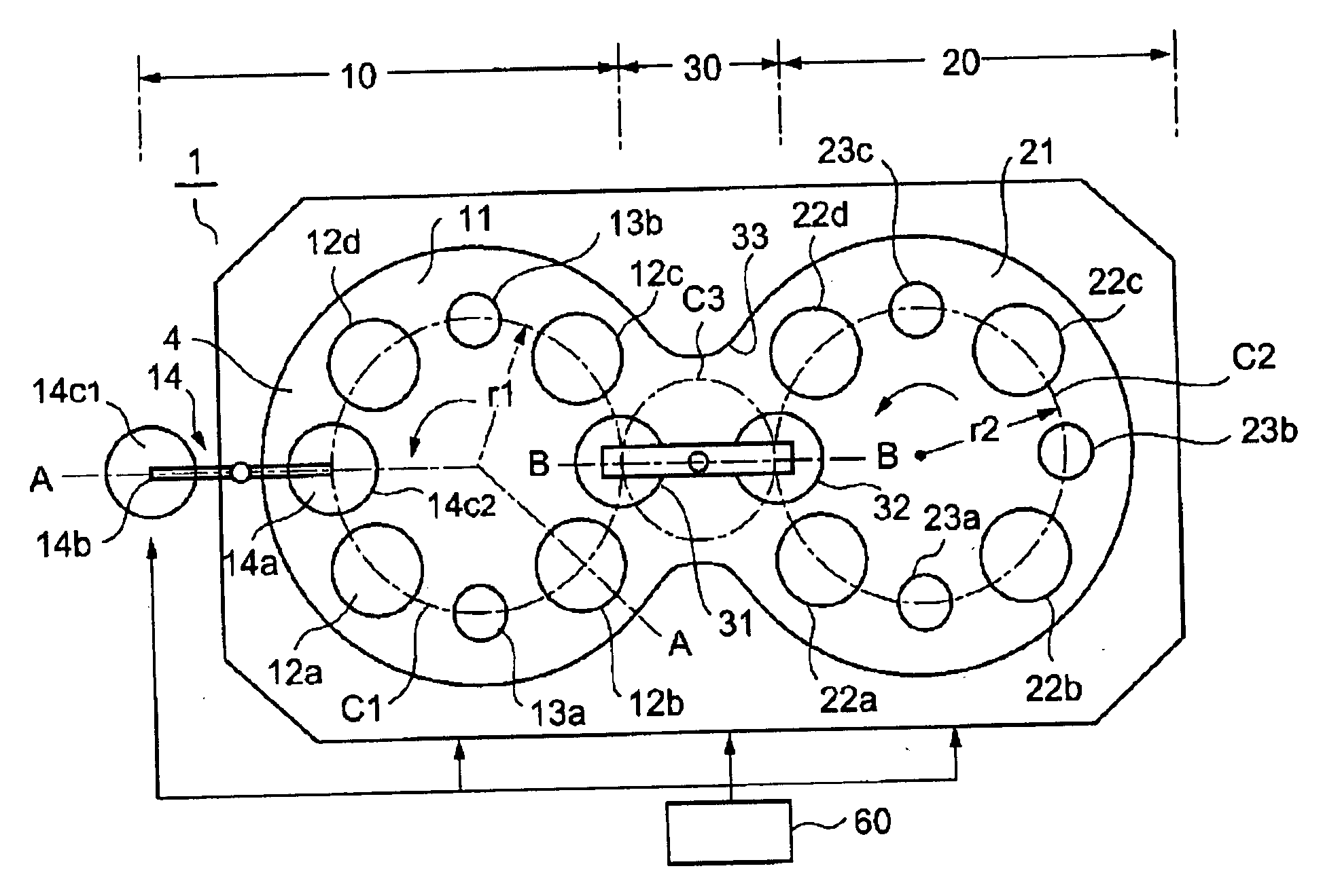
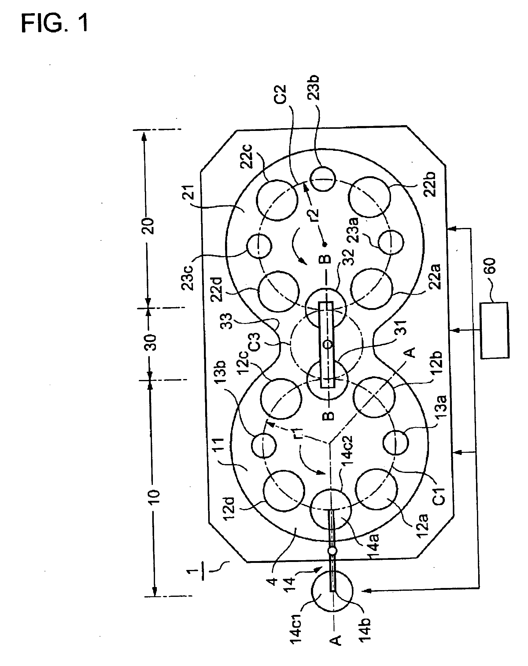
[0024]FIG. 1 to FIG. 3 illustrate an embodiment of the present invention. As shown in FIG. 1, a main chamber 1 capable of being evacuated in a vacuum state forms a guitar-shaped vacuum chamber 4 lengthened shallowly in the horizontal direction with a main body 2 and a top lid member 3. A first film-depositing process part 10 is divided by a first chamber 11 constituting one of the swelled portions, and a second film-depositing process part 20 is divided by a second chamber 21 constituting the other of the swelled portions. The first film-depositing process part 10 and the second film-depositing process part 20 are connected together through the neck portion of the guitar-shape, which defines a connecting part 30 forming the part between the first chamber and the second chamber to be a common vacuum space. Degree of vacuum is preferably matched to the best discharging condition of the film-depositing chamber, e.g. approximately 10−1 Pa.

[0025] In the first film-depositing process par...

embodiment 2

[0075] As shown in FIG. 6, arrangement of the first film-depositing process part 10 and the second film-depositing process part 20 of this embodiment is the same as that of the Embodiment 1, but the number of the film-depositing chambers in the second embodiment 20 is three (22a to 22c) different from the Embodiment 1 and the number of the cooling chambers is two (23a, 23b). The remaining parts are the same as the Embodiment 1, so that the same part is denoted by the same mark and explanation thereof will be omitted. Upon decreasing the number of the film-depositing chambers in the second film-depositing process part 20 compared to the first film-depositing process part 10 in accordance with various types of optical disks, the volume of the chamber can be set to be a bare minimum. Downsizing, reducing the installation area and facilitating the control can also be improved. Besides, at least one of the delivering positions 31 and 32 can double as a cooling chamber.

embodiment 3

[0076] As shown in FIG. 7, arrangement of the first film-depositing process part 10 and the second film-depositing process part 20 of this embodiment is the same as that of the Embodiment 1, but the load lock mechanism 14A is located at the position of the cooling chamber 13a in the Embodiment 1 and the cooling chamber 13c is located at the position of the load lock mechanism 14A in the Embodiment 1. The remaining parts are the same as the Embodiment 1, so that the same part is denoted by the same mark and explanation thereof will be omitted. This embodiment can be operated like the Embodiment 1.


PUM

PropertyMeasurementUnit
thicknessaaaaaaaaaa
thicknessaaaaaaaaaa
diameteraaaaaaaaaa

Abstract

To provide a vacuum processing apparatus applicable to various manufacturing processes, by efficiently and highly reliably stacking films of various types and thicknesses and by downsizing the manufacturing apparatus by suppressing size increase of the apparatus due to increase of the number of film forming chambers caused by increase and complexity of process steps. A vacuum processing apparatus is provided with a plurality of film forming process parts which are provided with rotating transfer tables and film forming chambers. The rotating transfer tables form a transfer path for a work to be processed, in chambers which can be vacuum-exhausted. The film forming chambers are provided for depositing a film on the work to be processed which is arranged and transferred along a circumference which has a rotating shaft of the rotating transfer table as a center. The vacuum processing apparatus is also provided with a connecting part which connects the film forming process parts so as to share a vacuum space between the chambers, and the work to be processed in the film forming process parts is mutually transferred in the vacuum. A load lock mechanism is provided in one of the film forming process part or in the connecting part.

Description

FIELD OF THE TECHNOLOGY [0001] The present invention relates to a vacuum processing device depositing continuously a multilayer film on a substrate of such an optical disk or an optical component. DESCRIPTION OF THE BACKGROUND TECHNOLOGY [0002] Optical disks such as the compact disk (CD) or the digital versatile disk (DVD) have been diversified recently, and therefore availability thereof has been still growing from an information medium of reading-only to an optical information medium capable of writing. Synthetic resin, typically polycarbonate, having a low mold shrinkage ratio or a low expansion coefficient is used for substrate materials of the optical disk. Information is recorded on the surface of the substrate as a pit row in the case of the read-only disk, and a guide groove to become the track for laser is formed on the surface of the substrate in the case of the disk capable of writing. A multilayer film containing a writing layer is deposited on the surface to constitute ...

Claims


Application Information

Patent Timeline
Patent Type & Authority Applications(United States)
IPC IPC(8): C23C14/56G11B7/26B05C11/02C23C14/00
CPCC23C14/56G11B7/265C23C14/568C23C14/566C23C14/54H01L21/67207
Inventor IKEDA, JIROTAKIZAWA, YOJI
Owner SHIBAURA MECHATRONICS CORP
Why Eureka
Try Eureka