Method of joining together dissimilar metal members

a metal member and dissimilar technology, applied in the field of joining together dissimilar metal members, can solve the problems of reliability of the joint, the inability to replace all the materials to form the body parts and other parts with aluminum materials, and the inability to avoid providing a so-called hybrid joint, so as to achieve the effect of preventing uneven qualities of the joint region and enhancing the strength of the junction

Inactive Publication Date: 2008-02-07
SUMITOMO LIGHT METAL INDS LTD
View PDF7 Cites 51 Cited by
  • Summary
  • Abstract
  • Description
  • Claims
  • Application Information

AI Technical Summary

Benefits of technology

[0012]The present invention has been made in the light of the situations described above. It is therefore an object of the invention to provide a method of joining together dissimilar metal members which can effectively improve soundness of a joint region of the members, by superposing plate-like parts of a plurality of metal members, which are formed of mutually different materials and have mutually different hardnesses, and performing a friction stir welding operation to the superposed parts, without any anxiety of causing galvanic corrosion.
[0017]In the method of joining together dissimilar metal members according to the present invention, there is employed or used the double-acting rotary tool as the rotary tool and the probe movable in the axial direction independently from the shoulder member. In this arrangement, after joining together the first and second members by an action of the friction stirring under solid phase, the probe is removed, and then the probe hole formed by the removal of the prove can be filled by the material flown from another part of the friction stir zone other than a part, from which the probe is removed. In this way, the probe hole is filled up, so that even if there are existed substances, in particular, oxides of a material of the second member existed on a surface of the second member, metal components of the second member, and / or components for a surface treatment, at an interface between the first and second members, the substances are buried by the material flown from another part of the friction stir zone other than the part, from which the probe is removed, and the substances are not exposed to the exterior of the members. According to this arrangement, even if the first member is come into contact with water, there is not caused any anxiety of composing a battery between the water and the metal components of the first member which leads to a generation of a galvanic corrosion.
[0018]In the present invention, the probe hole is not left at the friction stir zone, whereby there is avoided a problem of retaining excessive coating material on the thus obtained joint member of dissimilar metal members. In addition, the anxiety of the generation of the galvanic corrosion can also be effectively removed, and the quality of the joint region obtained by the friction stir welding is improved. Therefore, the soundness of the joint region can be advantageously enhanced.FEATURES OF THE INVENTION
[0027]In this feature, the cylindrical burr-restraining member is used, so that there can be restrained or prevented the generation of the burr, which is formed of materials pushed out of the friction stir zone because of an insertion of the probe. Also, the material pushed out from the friction stir zone is pushed back to the friction stir zone, because the cylindrical burr-restraining member is abutted with the surface of the first member. According to this arrangement, there are effectively prevented oxides and other metal components from being flown to the surface of the first member by a plastic flow along an interface between the surface of the second member and the friction stir zone, whereby the oxides and other metal components are retained in the friction stir zone. Accordingly, there can be effectively removed an anxiety of causing the galvanic corrosion, which may be caused depending on kinds of the metal components moved to the surface of the second member along the interface.
[0031]In the method according to the above feature (7), there is regulated the distance between the tip of the probe projected out of the rotary tool and the surface of the second member, and the tip of the probe is positioned right above the surface of the second member. In this arrangement, only the first member is stirred, and there can be effectively made a newly-formed surface at the interface between the first and second members. Accordingly, there can be advantageously enhanced a strength of the junction between these members, and can be effectively prevented qualities of the joint region from being uneven.

Problems solved by technology

However, it is difficult to replace all the materials to form the body parts and the other parts with aluminum materials.
For this reason, when there is used the member formed of the aluminum material, there cannot avoid providing a so-called hybrid joint, i.e., a joint between a member formed of a steel material and the member formed of the aluminum material, which materials are dissimilar metals to each other.
Conventionally, there has been a problem in joining together metal members by a generally used melt welding method.
However, each of these methods inherently has problems in terms of an efficiency of the joining operation, a reliability of the joint, a design of the joint, and a cost of the joint, to a greater or lesser extent, which would be a hindrance to put the method to a practical use.
In this case, there are inherent anxieties of causing problems such as a problem of retaining excessive coating material at the bottom of the hole which is a trace of the probe, and further causing corrosion because of the existence of the hole.
In such a case, there is an anxiety that there may be caused what is called galvanic corrosion (electrical corrosion) or bimetallic corrosion between the above-mentioned components and the aluminum member of the aluminum plate, by an entry of water etc. to the probe hole.
For this reason, if this method is applied to join together a member formed of the aluminum material and a member formed of the steel material, there is a problem that the probe would be worn by the member formed of the steel material, so that the lifetime of the jig would be extremely short.

Method used


Image

  • Method of joining together dissimilar metal members
  • Method of joining together dissimilar metal members
  • Method of joining together dissimilar metal members

Examples


examples

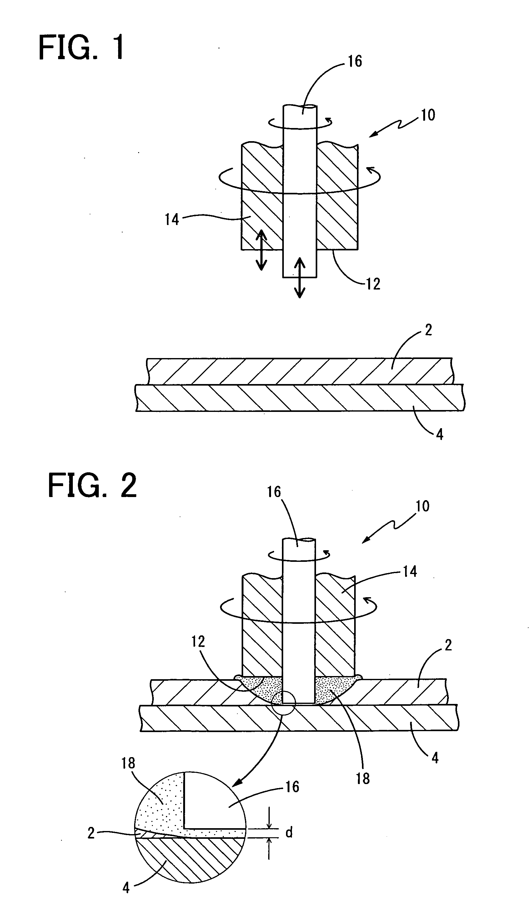
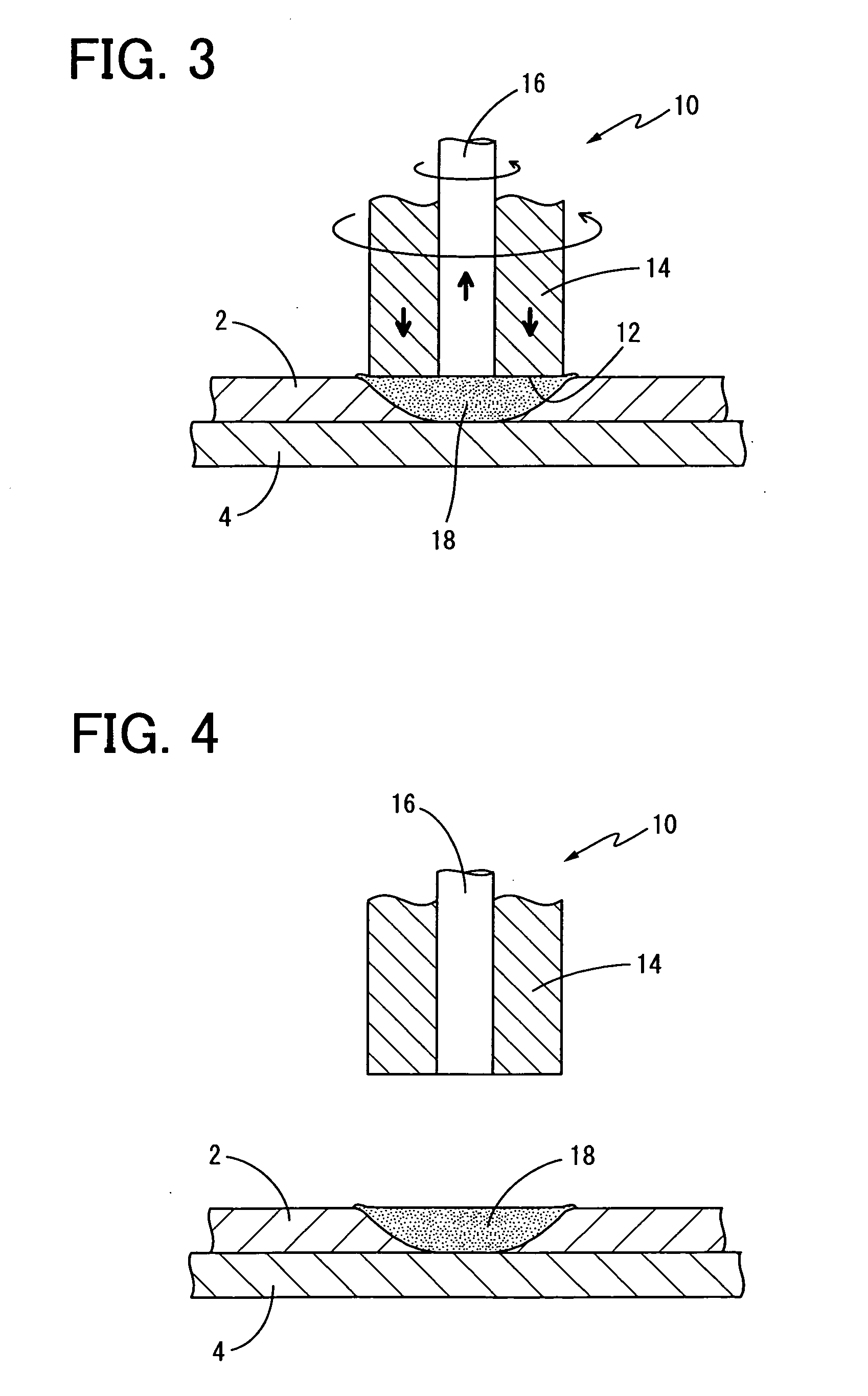
[0072]Initially, there was prepared, as the first member 2 formed of a soft metal, a plate member formed of 6000 series aluminum material (AA6016-T4) having a thickness of 1 mm. There was also prepared, as the second member 4 formed of a hard metal, a plate member formed of a steel material (SPCC) having a thickness of 1 mm.

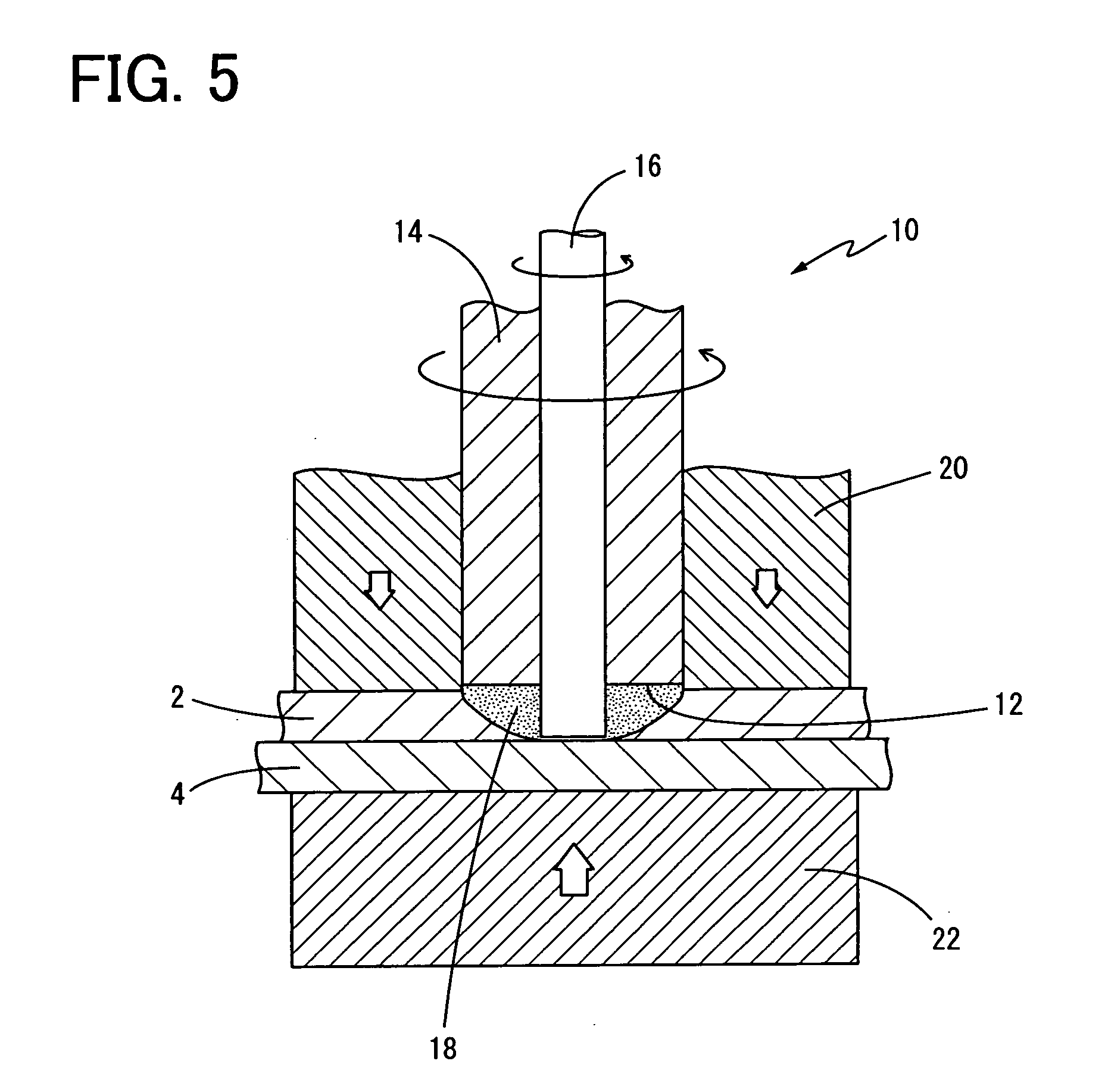
[0073]Subsequently, the aluminum plate 2 and the steel plate 4 were superposed on each other. The friction stir welding operation according to the present invention was implemented from a side of the aluminum plate 2, by using the rotary tool 10, wherein a cylindrical steel clamp as the burr-restraining member 20 was inserted, so that the cylindrical steel clamp was brought into engagement with a peripheral portion of the rotary tool 10, as shown in FIG. 5.

[0074]In detail, the backing jig 22 was butted together with a back surface of the lower metal plate 4, and in this way, the plates 2, 4 were supported on each other. The cylindrical steel clamp which had an ex...


PUM

PropertyMeasurementUnit
thicknessaaaaaaaaaa
thicknessaaaaaaaaaa
diameteraaaaaaaaaa

Abstract

A method of joining together dissimilar metal members, by superposing a first member formed of an aluminum plate and a second member formed of a steel plate on each other, and performing a friction stir welding operation by rotating a probe located coaxially with and at an end of a shoulder member of a rotary tool, while the probe is inserted into the first member in a way that a tip of the prove reaches right above the second member, wherein a double-acting rotary tool is used as the rotary tool, and after the friction stir welding operation is performed, the probe is removed from thus formed friction stir zone while a probe hole formed by the removal of the prove is filled by a material flown from another part of the friction stir zone other than a part, from which the probe is removed.

Description

[0001]This application is based on Japanese Patent Application No. 2005-056939 filed on Mar. 2, 2005, the contents of which are incorporated hereinto by reference.BACKGROUND OF THE INVENTION[0002]1. Field of the Invention[0003]The present invention relates to a method of joining together dissimilar metal members, and particularly to a technique which can improve a soundness of the joint region when plate-like portions of two metal members, which are formed of mutually different materials and have mutually different hardnesses, are joined together.[0004]2. Discussion of Related Art[0005]Recently, there are required restriction of generation of harmful gasses and carbon dioxide discharged from an automobile, and also required reduction of fuel expenses, from a point of view of protecting the global environment and saving the energy. Reduction in weight of the automobile is the most effective to meet the requirements, so that there are actively reviewed replacements of steel materials ...

Claims


Application Information

Patent Timeline
Patent Type & Authority Applications(United States)
IPC IPC(8): A47J36/02
CPCB23K2203/20B23K20/1255B23K2103/20
Inventor KUMAGAI, MASAKITANAKA, KOJI
Owner SUMITOMO LIGHT METAL INDS LTD
Why Eureka
Try Eureka