Liquid crystal composition and liquid crystal display device

a liquid crystal composition and display device technology, applied in liquid crystal compositions, thin material processing, chemistry apparatus and processes, etc., can solve the problems of device long service life and small electric power consumption, and achieve high UV light stability, small viscosity, and large specific resistance

Active Publication Date: 2008-02-07
JNC PETROCHEM CORP +1
View PDF13 Cites 25 Cited by
  • Summary
  • Abstract
  • Description
  • Claims
  • Application Information

AI Technical Summary

Benefits of technology

[0015]One advantage of the invention is to provide a liquid crystal composition that satisfies at least one characteristic among the characteristics such as a high maximum temperature of a nematic phase, a low minimum temperature of a nematic phase, a small viscosity, a large optical anisotropy, a large dielectric anisotropy, a large specific resistance, a high stability to ultraviolet light, a high stability to heat and so forth. Another advantage of the invention is to provide a liquid crystal composition that is properly balanced regarding at least two characteristics among the many characteristics. Another advantage of the invention is to provide a liquid crystal display device that contains the liquid crystal composition. One aspect of the invention is to provide a liquid crystal composition that has a large optical anisotropy, a large dielectric anisotropy, a high stability to ultraviolet light and so forth, and is to provide an AM device that has a short response time, a large voltage holding ratio, a large contrast ratio, a long service life and so forth.
[0017]1. A liquid crystal composition having a nematic phase including three components, wherein the first component is at least one compound selected from the group of compounds represented by Formula (1), the second component is at least one compound selected from the group of compounds represented by Formula (2), and the third component is at least one compound selected from the group of compounds represented by Formulas (3-1) and (3-2):
[0019]3. The liquid crystal composition according to item 1 or 2, wherein the second component is at least one compound selected from the group of compounds represented by Formulas (2-1) to (2-7):
[003

Problems solved by technology

A large dielectric anisotropy of the composition contributes to a low threshold voltage, a small electric power c

Method used


Image

  • Liquid crystal composition and liquid crystal display device
  • Liquid crystal composition and liquid crystal display device
  • Liquid crystal composition and liquid crystal display device

Examples


example 1

[0089]The composition of Example 1 had a small rotation viscosity as compared to the composition of Comparative Example 1.

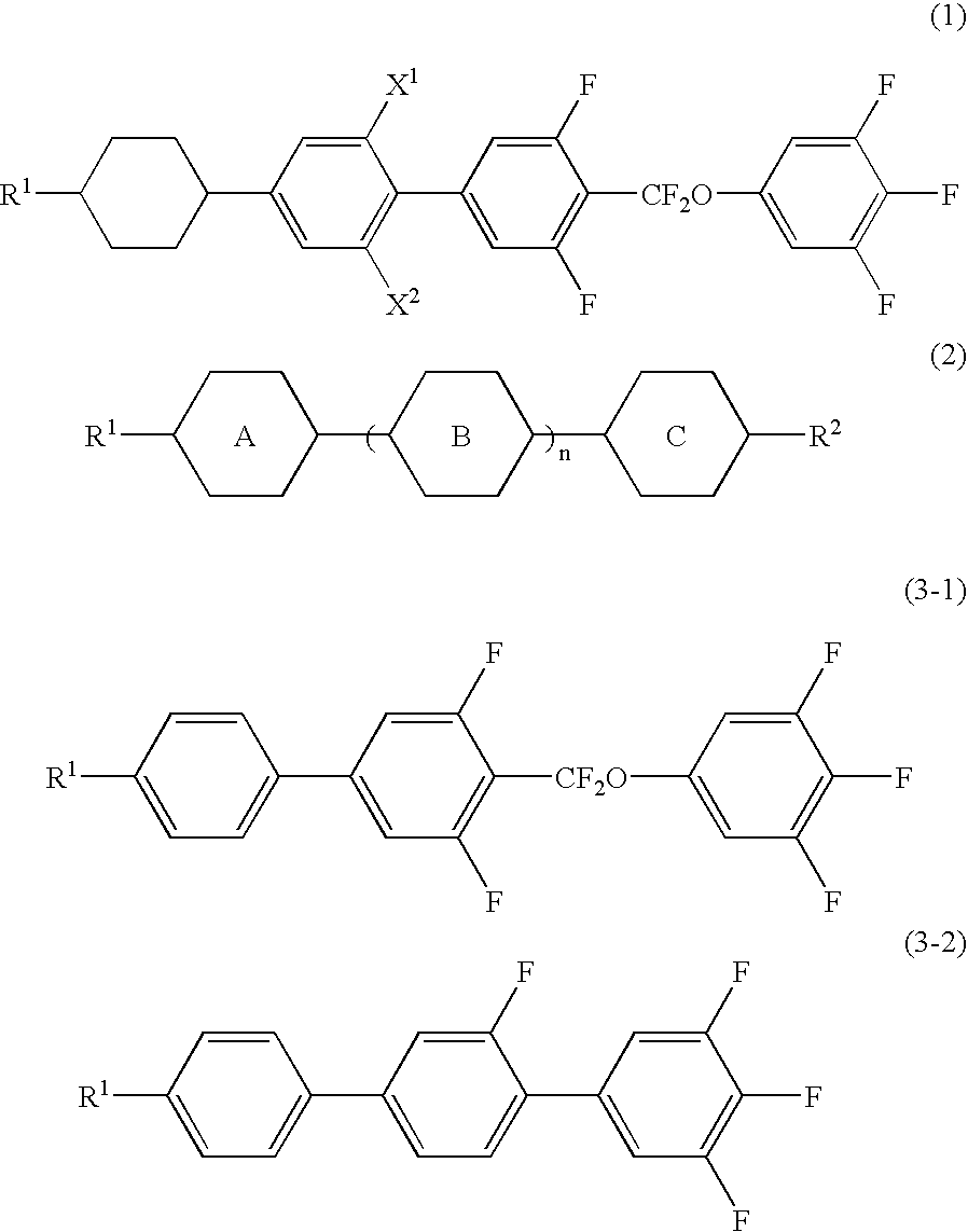
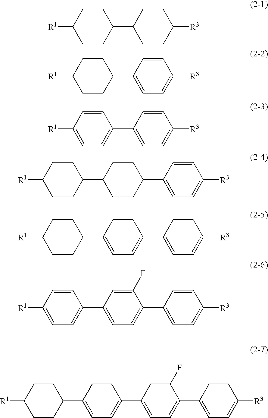
3-HBB(F,F)XB(F,F)-F(1-1)10%5-HBB(F,F)XB(F,F)-F(1-1)9%3-HH-V(2-1-1)40%3-HH-V1(2-1-1)10%5-HH-V(2-1-1)10%3-HHB-1(2-4-1)5%V-HHB-1(2-4-1)10%3-BB(F,F)XB(F,F)-F(3-1-1)6%

[0090]NI=79.7° C.; Tc≦−20° C.; Δn=0.082; Δε=3.1; Vth=2.19 V; γ1=43.2 mPa.s; τ=8.3 ms; VHR-1=99.1%; VHR-2=98.3%; VHR-3=98.2%.

example 2

[0091]The composition of Example 2 had a small rotation viscosity as compared to the composition of Comparative Example 2.

3-HBB(F,F)XB(F,F)-F(1-1)13%3-HH-V(2-1-1)37%3-HH-V1(2-1-1)10%5-HH-V(2-1-1)12%3-HBB-2(2-5-1)7%1V-HBB-2(2-5-1)8%3-BB(F,F)XB(F,F)-F(3-1)7%3-BB(F)B(F,F)-F(3-2-1)6%

[0092]NI=75.8° C.; Tc≦−20° C.; Δn=0.095; Δε=3.7; Vth=2.08 V; γ1=44.1 mPa.s; τ=8.6 ms; VHR-1=99.2%; VHR-2=98.1%; VHR-3=98.2%.

example 3

[0093]The composition of Example 3 had a small rotation viscosity as compared to the composition of Comparative Example 3.

3-HBB(F,F)XB(F,F)-F(1-1)14%5-HBB(F,F)XB(F,F)-F(1-1)6%3-HH-V(2-1-1)39%3-HH-V1(2-1-1)11%5-HH-V(2-1-1)10%2-BB(F)B-3(2-6-1)10%2-BB(F)B-5(2-6-1)5%3-BB(F)B(F,F)-F(3-2-1)5%

[0094]NI=77.0° C.; Tc≦−20° C.; Δn=0.106; Δε=3.3; Vth=2.15 V; γ1=45.2 mPa.s; τ=8.7 ms; VHR-1=99.2%; VHR-2=98.3%; VHR-3=98.3%.


PUM


Abstract

A liquid crystal composition having a nematic phase that includes three components, wherein the first component is a specific four-ring compound having a bonding group of —CF2O— and trifluorobenzene, the second component is a specific compound having a small viscosity, and the third component is a specific three-ring compound having trifluorobenzene, and a liquid crystal display device including the composition.

Description

CROSS REFERENCE TO RELATED APPLICATIONS[0001]This application claims priority under 35 U.S.C. § 119 to Japanese Patent Application No. JP 2006-214290, filed Aug. 7, 2006, which is expressly incorporated herein by reference in its entirety.BACKGROUND OF THE INVENTION[0002]1. Field of the Invention[0003]The invention relates to a liquid crystal composition suitable for use in an active matrix (AM) device, and an AM device containing the composition. In particular, the invention relates to a liquid crystal composition having a positive dielectric anisotropy, and to a device having a TN (twisted nematic) mode, an OCB (optically compensated bend) mode or an IPS (in-plane switching) mode containing the composition.[0004]2. Related Art[0005]In a liquid crystal display device, classification based on an operating mode of liquid crystals includes phase change (PC), twisted nematic (TN), super twisted nematic (STN), electrically controlled birefringence (ECB), optically compensated bend (OCB)...

Claims


Application Information

Patent Timeline
IPC IPC(8): C09K19/30
CPCC09K19/3066C09K19/42C09K19/44C09K2019/0466Y10T428/10C09K2019/301C09K2019/3016C09K2019/3025Y10T428/1036C09K2019/123C09K2323/00C09K2323/03
Inventor SAITO, MASAYUKI
Owner JNC PETROCHEM CORP
Why Eureka
Try Eureka