High-Pressure Fuel Pump Drive Circuit for Engine
- Summary
- Abstract
- Description
- Claims
- Application Information
AI Technical Summary
Benefits of technology
Problems solved by technology
Method used
Image
Examples
example 1
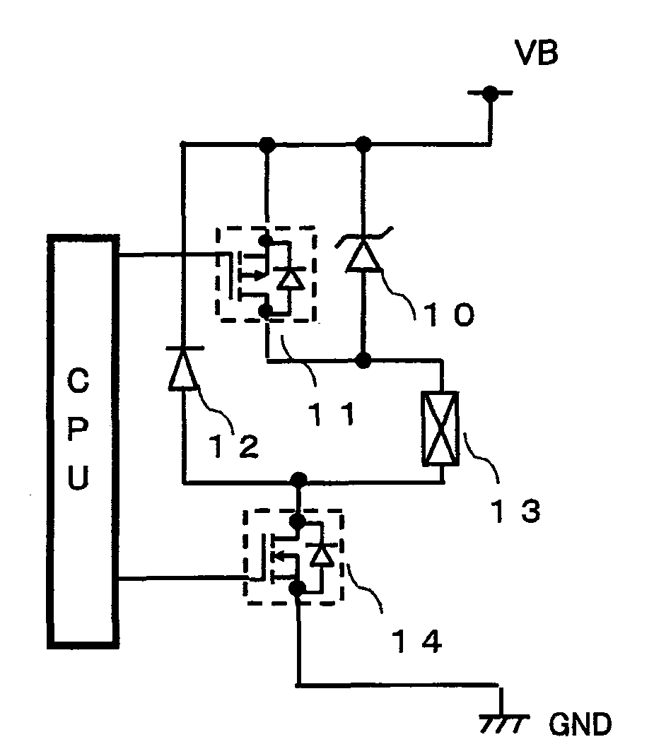
[0031]FIG. 4 illustrates a circuit configuration of a high-pressure fuel pump drive circuit for engine according to Example 1.
[0032]In this circuit, the solenoid 13 of high-pressure pump is connected with the drain of switching MOSFET (Nch) 14, and the cathode of flywheel diode 12 is connected with the source voltage VB and the anode of flywheel diode 12 is connected with the solenoid. Further, the cathode of Zener diode 10 is connected with the VB and the anode thereof is connected with the solenoid coil. The MOSFET (Pch) 11 is connected, in parallel, with the Zener diode. When an input voltage is impressed to the gates of the MOSFET (Pch) 11 and the MOSFET (Nch) 14, not only the MOSFET (Pch) 11 but also the MOSFET (Nch) 14 is turned ON, permitting an electric current IL to flow into the solenoid coil 13. At this moment, the drain voltage VD of MOSFET (Nch) 14 is caused to fall from the VB to about zero volt and, at the same time, the electric current IL flowing through the solenoi...
example 2
[0037]FIG. 6 illustrates a circuit configuration of a high-pressure fuel pump drive circuit for engine according to Example 2.
[0038]In this circuit, the solenoid coil 20 of high-pressure pump is connected with the drain of switching MOSFET (Pch) 19, and the cathode of flywheel diode 21 is connected with the drain of switching MOSFET (Pch) 19 and the anode of flywheel diode 21 is connected with the GND. Further, the cathode of Zener diode 22 is connected with the solenoid coil 20 and the anode thereof is connected with the GND. The MOSFET (Nch) 23 is connected, in parallel, with the Zener diode.
[0039]When an input voltage is impressed to the MOSFET (Pch) 19 and the MOSFET (Nch) 23, not only the MOSFET (Pch) 19 but also the MOSFET (Nch) 23 is turned ON, permitting an electric current IL to flow into the solenoid coil 20. At this moment, the drain voltage VD of MOSFET (Pch) 19 is caused to fall from the source voltage VB to about zero volt and, at the same time, the electric current IL...
example 3
[0043]FIG. 8 illustrates a circuit configuration of a high-pressure fuel pump drive circuit for engine according to Example 3.
[0044]In this circuit, the solenoid coil 30 of high-pressure pump is connected with the drain of switching MOSFET (Nch) 35, and the anode of flywheel diode 32 is connected with the drain of MOSFET (Nch) 35 and the cathode of flywheel diode 32 is connected with the source of MOSFET (Pch) 28. Further, the anode of Zener diode 31 is connected with the source voltage VB and the cathode thereof is connected with the cathode of flywheel diode 32. The MOSFET (Pch) 28 is connected, in parallel, with the Zener diode. When an input voltage is impressed to the gates of the MOSFET (Pch) 28 and the MOSFET (Nch) 35, not only the MOSFET (Pch) 28 but also the MOSFET (Nch) 35 is turned ON, permitting an electric current IL to flow into the solenoid coil 30. At this moment, the drain voltage VD of MOSFET (Nch) 35 is caused to fall from the VB to about zero volt and, at the sam...
PUM
 Abstract
Description
Claims
Application Information
 - R&D
- Intellectual Property
- Life Sciences
- Materials
- Tech Scout
- Unparalleled Data Quality
- Higher Quality Content
- 60% Fewer Hallucinations
Browse by: Latest US Patents, China's latest patents, Technical Efficacy Thesaurus, Application Domain, Technology Topic, Popular Technical Reports.
© 2025 PatSnap. All rights reserved.Legal|Privacy policy|Modern Slavery Act Transparency Statement|Sitemap|About US| Contact US: help@patsnap.com


