Phase detection apparatus and method, phase locked loop circuit and control method thereof, and signal reproducing apparatus and method

a phase detection and control method technology, applied in the field of phase detection and phase locked loops, can solve the problems of optical disc reproducing system malfunction, serious interference in the waveform of an rf signal reproduced by an hd optical disc reproducing system, and the inability to detect a zero-crossing point of the reproduced rf signal, so as to reduce the hardware scale

Inactive Publication Date: 2008-02-07
SAMSUNG ELECTRONICS CO LTD
View PDF3 Cites 16 Cited by
  • Summary
  • Abstract
  • Description
  • Claims
  • Application Information

AI Technical Summary

Benefits of technology

[0016]Aspects of the present invention provide a phase detection apparatus and method, a phase locked loop circuit and a control method thereof, and a signal reproducing apparatus and

Problems solved by technology

However, the waveform of an RF signal reproduced by an HD optical disc reproducing system is seriously affected by inter-symbol interference (ISI).
If a reproduced RF signal is affected by ISI, it may be impossible to detect a zero-crossing point of the reproduced RF signal.
When a reproduced RF signal is affected by ISI to the extent that its zero-crossing point cannot be detected, this condition is called a “high ISI condition.” The channel characteristics of an RF signal reproduced under a high ISI condition are sensitive to even low levels of noise, thus leading to a malfunction of the optical disc reproducing system.
Accordingly, there is a strong possibility that the ze

Method used


Image

  • Phase detection apparatus and method, phase locked loop circuit and control method thereof, and signal reproducing apparatus and method
  • Phase detection apparatus and method, phase locked loop circuit and control method thereof, and signal reproducing apparatus and method
  • Phase detection apparatus and method, phase locked loop circuit and control method thereof, and signal reproducing apparatus and method

Examples


case 1

1) Case 1

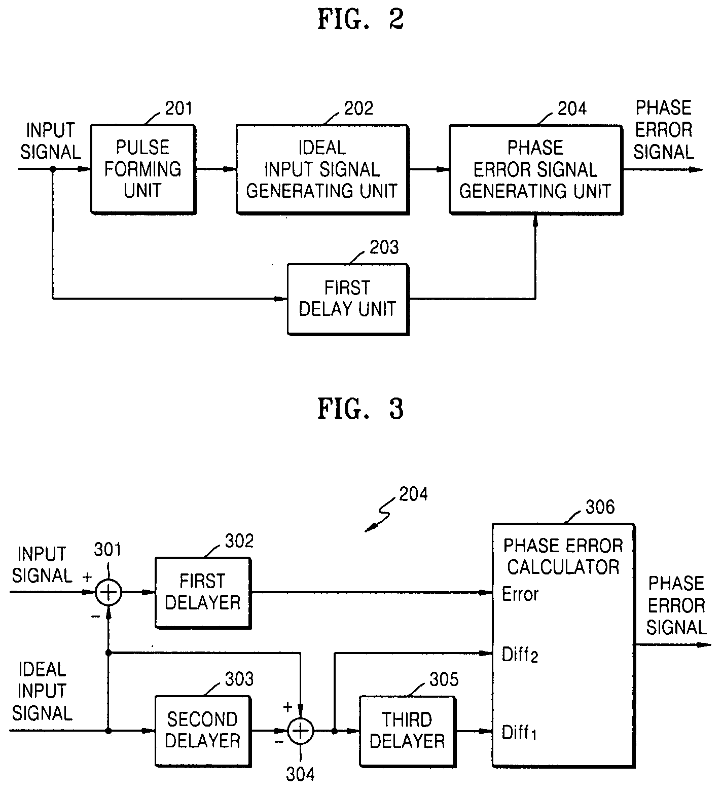
Diff1>Threshold, Diff2>Threshold: phase error info=Error / (Diff1+Diff2)

case 2

2) Case 2

Diff1<-Threshold, Diff2<-Threshold: phase error info=Error / (Diff1+Diff2)

case 3

3) Case 3

Otherwise: phase error info=0  (3)

where the threshold is a non-negative constant value.

[0079]FIGS. 4A, 4B, 4C, 4D, 4E, 4F, 4G, 4H, 4I, and 4J are diagrams illustrating the operating principle of the phase error calculator 306 illustrated in FIG. 3. FIGS. 4A, 4B and 4C illustrate analog input signals (e.g., analog RF signals) with a rising edge, while FIGS. 4D, 4E, and 4F illustrate analog input signals (e.g., analog RF signals) with a falling edge.

[0080]If a real input signal is sampled according to a phase locked loop (PLL) clock signal without a phase error, a sampled input signal at the rising or falling edge is statistically identical to the ideal input signal as illustrated in FIGS. 4A and 4D. In this case, an expected error between the real input signal and the ideal input signal is “0.”

[0081]If a real input signal is sampled according to a PLL clock signal with a delayed phase error, the sampled input signal at the rising edge is statistically greater than the ideal ...


PUM


Abstract

A phase detection apparatus and method, a PLL circuit and a control method thereof, and a signal reproducing apparatus and method which can provide anti-noise and anti-ISI characteristics while reducing the scale of hardware used in an optical disc reproducing system having high-ISI conditions include a pulse forming unit to detect binary data of an input signal, an ideal input signal generating unit to generate an ideal input signal based on the detected binary data, and a phase error signal generating unit to generate a phase error signal based on the input signal and the ideal input signal.

Description

CROSS-REFERENCE TO RELATED APPLICATION[0001]This application claims the benefit of Korean Application No. 2006-73821, filed Aug. 4, 2006, in the Korean Intellectual Property Office, the disclosure of which is incorporated herein by reference.BACKGROUND OF THE INVENTION[0002]1. Field of the Invention[0003]Aspects of the present invention relate to phase detection and phase locked loops (PLLs), and more particularly, to a phase detection apparatus and method, a PLL circuit and a control method thereof, and a signal reproducing apparatus and method that are suitable for an optical disc reproducing system.[0004]2. Description of the Related Art[0005]Optical disc reproducing systems reproduce data recorded on optical discs such as compact discs (CDs), digital versatile discs (DVDs), blue-ray discs (BDs), and high-definition DVDs (HD-DVDs). In particular, optical disc reproducing systems that reproduce data recorded on BDs or HD-DVDs can be called “HD optical disc reproducing systems.”[00...

Claims


Application Information

Patent Timeline
IPC IPC(8): H04B17/00H03M1/00
CPCG11B20/10009G11B20/10222H03L7/087H03L7/06G11B20/10425G11B7/09G11B20/24G11B20/10
Inventor ZHAO, HULPARK, HYUN-SOO
Owner SAMSUNG ELECTRONICS CO LTD
Why Eureka
Try Eureka