
Catheter system and method of use thereof

a catheter system and catheter tip technology, applied in the field of catheter systems, can solve the problems of significant consumption of time required for rf catheterization of these and other tissue structures with a peak, ridge or ring shape, and the tip of the catheter to slip off the target tissue, so as to increase maneuverability and ease of placement, and enhance the flexibility of the catheter shaft and tip area.

Inactive Publication Date: 2008-02-07
MACHELL CHARLES H
View PDF17 Cites 44 Cited by
  • Summary
  • Abstract
  • Description
  • Claims
  • Application Information

AI Technical Summary

Benefits of technology

[0009] It is an object of the present invention to provide a device that will make it easier and quicker to apply RF energy to a ring, peak, ridge or other non-planar tissue structure. SUMMARY OF THE INVENTION
[0015] This and other objects are provided in the catheter system having only four electrodes, a tip and a ring ablation electrode and a pair of recording electrodes, to enhance flexibility of the catheter shaft and tip area and therefore increase maneuverability and ease of placement on a ring structure.

Problems solved by technology

In treating conditions of the mitral and / or tricuspid annulus with the RF catheter described above, it is often difficult to maintain a distal ablation electrode adjacent the ring structure as often a slight amount of pressure against the ring will cause the tip of the catheter to slip off the target tissue.
As a result, a significant amount of time required for RF catheterization of these and other tissue structures with a peak, ridge or ring shape is consumed with proper location of the catheter tip adjacent the target area.
When the location of the target area is close to or at a peak, ridge or ring, the tip electrode must be carefully placed on the target site and this careful placement is time consuming.

Method used


Image

  • Catheter system and method of use thereof
  • Catheter system and method of use thereof
  • Catheter system and method of use thereof

Examples


Embodiment Construction

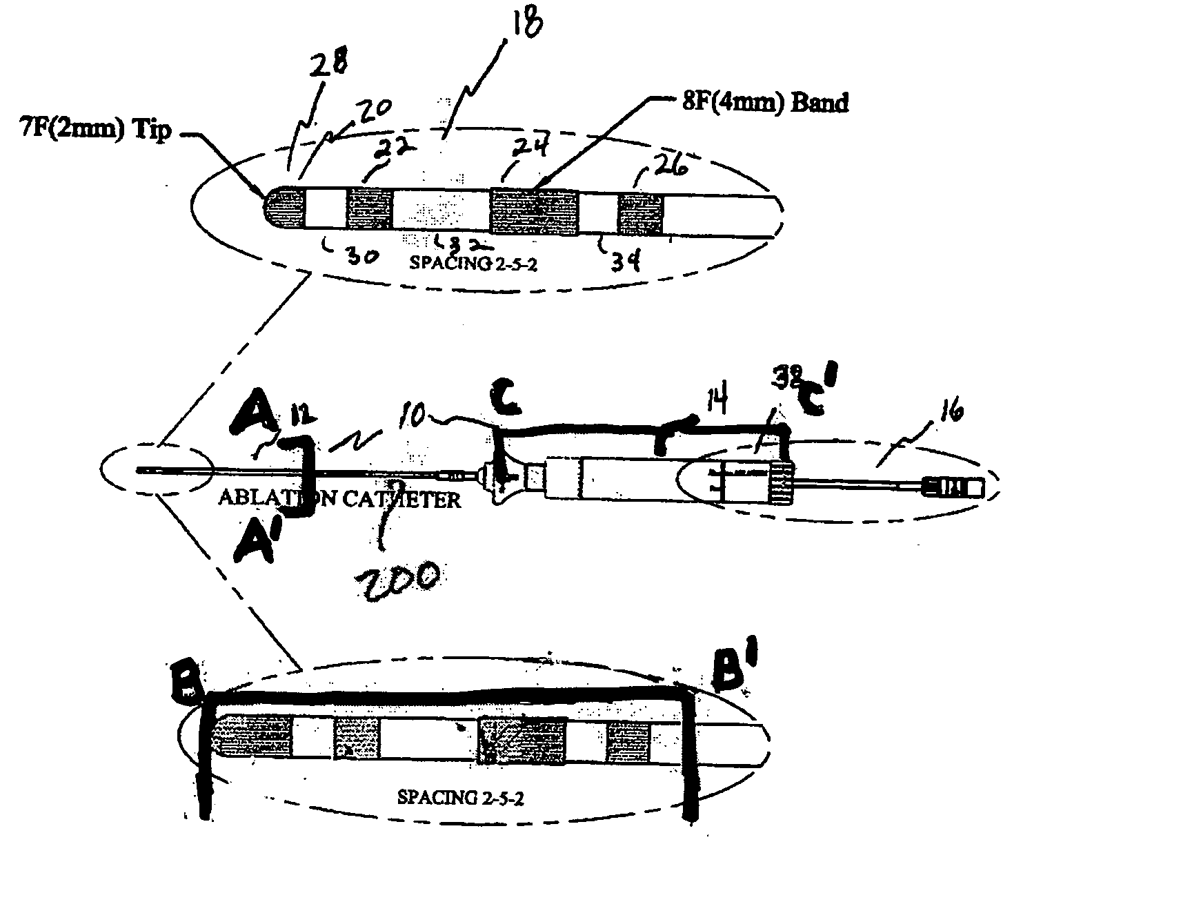
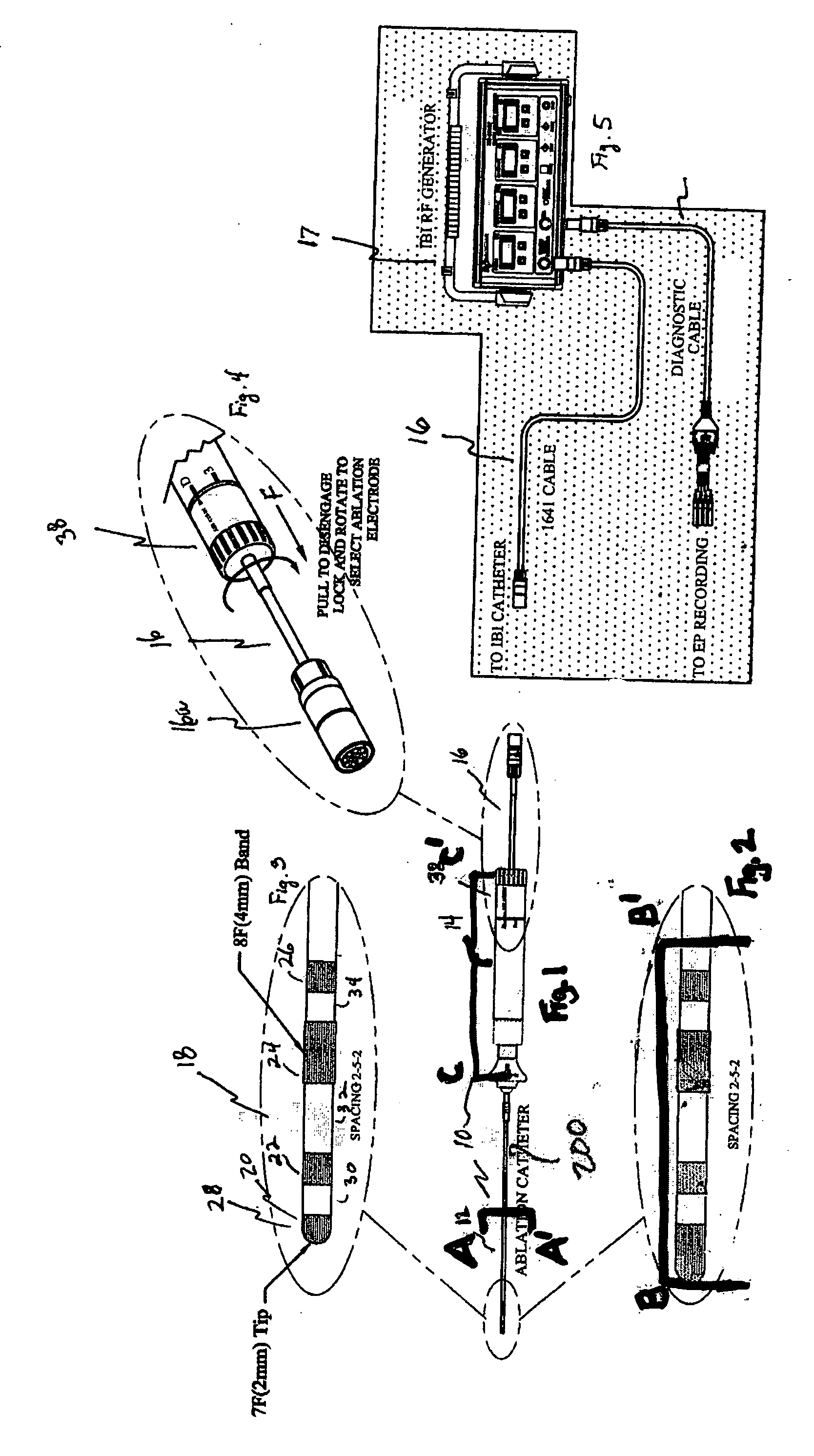
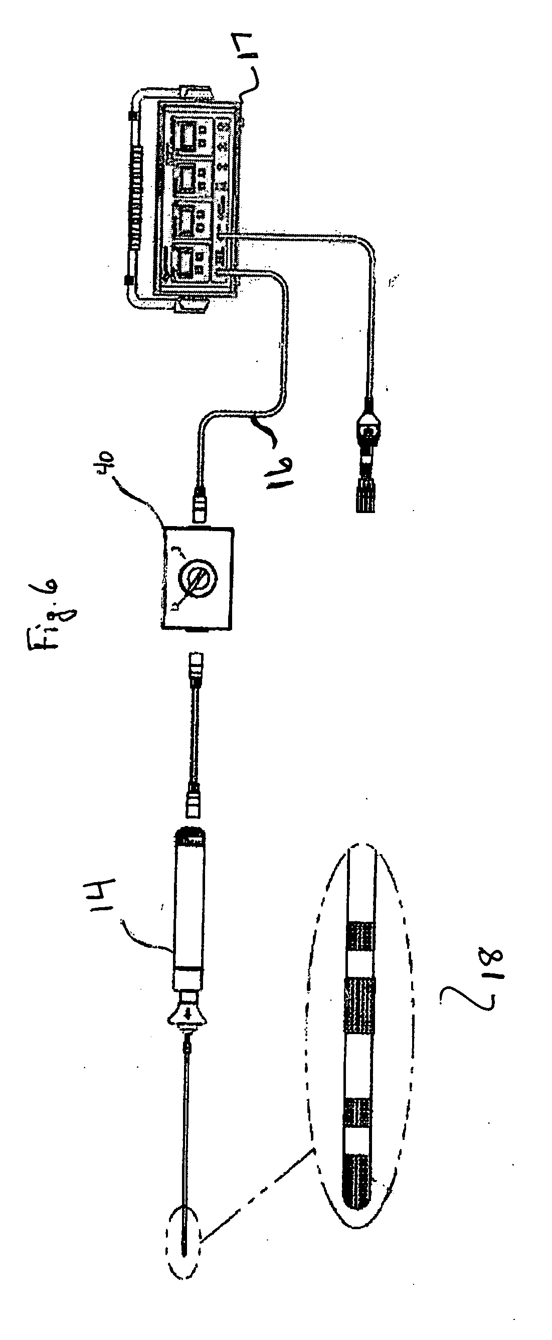
[0029]FIG. 1 illustrates applicant's catheter 10, the catheter including a cylindrical catheter shaft 12 engaged with a catheter handle 14. A catheter cable 16 connects the catheter to a radio frequency RF generator 17 (see FIG. 5) for electronic engagement of the catheter with the RF generator.

[0030] The catheter shaft 12 includes a shell 200, fabricated from a nylon, urethane or other plastic, bio-compatible material and a polyamide layer 202 forming electrode lumens 112 and control lumens 114, therein. The electrode lumens and the control lumens are essentially long hollow tubes that traverse the length of the catheter shaft 12.

[0031] Turning now to FIG. 2, it is seen that the external portion of applicant's catheter shaft 12 includes a distal end 18 typically comprised of a multiplicity of electrodes (preferably four), here electrodes 20, 22, 24, and 26. Distal end 18 includes a tip 28. As set forth in the Figures, tip 28 may be comprised of an electrode, here distal or tip el...


PUM


Abstract

A catheter system including a catheter having a shaft ablation electrode. An embodiment discloses a switch in a catheter having both a tip and a shaft ablation electrode for switching the delivery or RF energy between the two ablation electrodes. Further, a method of using a catheter having a shaft ablation electrode for treating heart disease and disorders. The method includes use of the shaft ablation electrode for ablation of tissue on a ring or ridge shaped structure.

Description

[0001] This application claims priority to and incorporates herein by reference U.S. Provisional Patent Application Ser. No. 60 / 833,649, filed Jul. 27, 2006.FIELD OF THE INVENTION [0002] Catheter systems, including catheter systems for use in diagnosis and treatment, as by RF energy, of organs in the human body, including the heart. BACKGROUND OF THE INVENTION[0003] Ablation is a medical term that refers to any procedure performed to destroy diseased or damaged tissue in the human body. Catheter ablation is a technique in which a thin tube or catheter is inserted percutaneously and manipulated through the blood vessels to the site of origin of an arrhythmia. Target tissue is heated by applying energy through the catheter, usually using radiofrequency current, to destroy cardiac tissue responsible for the genesis of arrhythmias. [0004] Radiofrequency is a widely used and effective form of energy applied during catheter ablation. Alternating current, typically between 300-750 kHz, is ...

Claims


Application Information

Patent Timeline
IPC IPC(8): A61B18/18
CPCA61B18/1492A61B2018/1467A61B2018/00958
Inventor MACHELL, CHARLES H.
Owner MACHELL CHARLES H
Learn More