
Knee joint prosthesis used in total knee arthroplasty

a knee joint and total knee arthroplasty technology, applied in the field of knee joint prosthesis, can solve the problems of high loosening rate, high loosening rate, and high stress on the knee joint, so as to increase the life of the knee joint prosthesis, not sacrifice knee stability, and reduce the amount of stress

Inactive Publication Date: 2008-02-07
STCHUR ROBERT P
View PDF22 Cites 32 Cited by
  • Summary
  • Abstract
  • Description
  • Claims
  • Application Information

AI Technical Summary

Benefits of technology

[0011]An even further object of the present invention is to provide tibial bearing inserts and tibial components to be used in total knee arthroplasty that reduce the amount of stress imparted on the bone-cement or bone-prosthesis interface.
[0012]Another object of the present invention is to provide tibial bearing inserts and tibial components to be used in total knee arthroplasty that significantly increase the survivorship of the knee prosthesis.
[0013]An even further object of the present invention is to provide tibial bearing inserts and tibial components to be used in total knee arthroplasty that do not sacrifice knee stability.
[0014]A further object of the present invention is to provide tibial bearing inserts and tibial components to be used in total knee arthroplasty could allow for greater flexion.
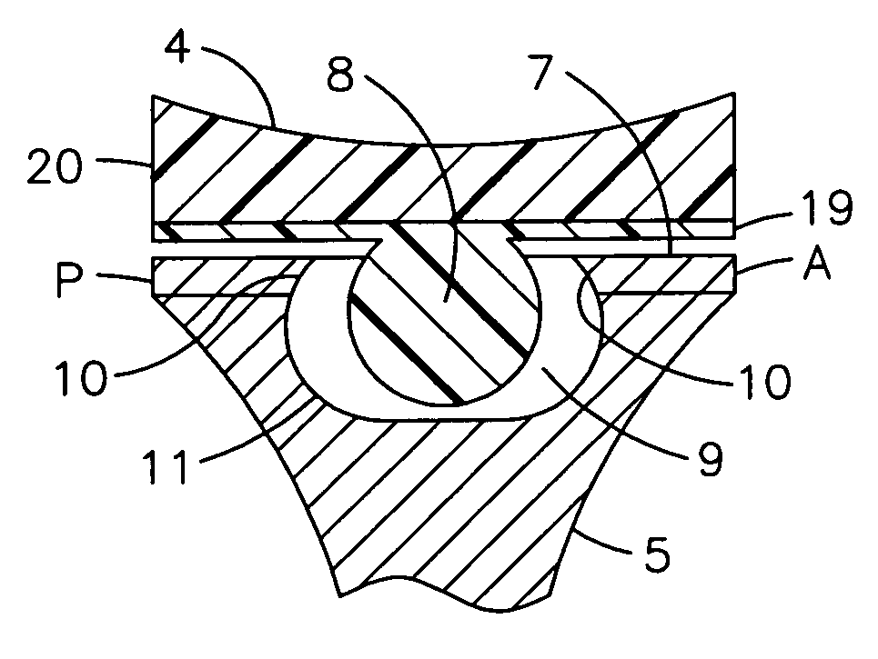
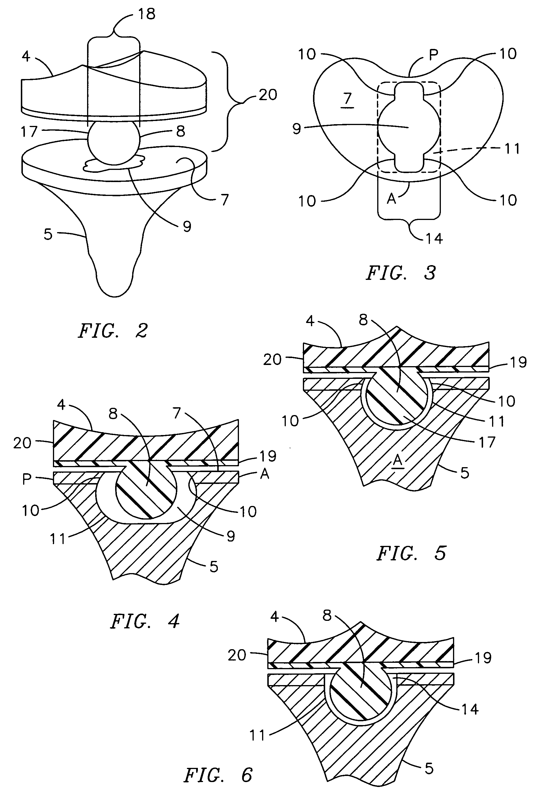
[0015]The present invention fulfills the above and other objects by providing tibial bearing inserts and tibial components having predetermined corresponding shapes that allow for an additional degree of freedom in both an anterior-posterior direction and rotation. The tibial bearing inserts include a predeterminedly-shaped extension, such as a sphere, disk or trapezoid, that extends downwardly from the bearing. The tibial components include a socket having a corresponding predetermined shape of the extension and retaining edges located at a top of the socket so the extension may be “dropped into” the socket and therein retained. In this manner, disengagement of the tibial bearing insert at extremes of anterior or posterior translation of the bearing relative to the tibial component is prevented without affected the translation and rotation of the tibial component and tibial bearing insert.

Problems solved by technology

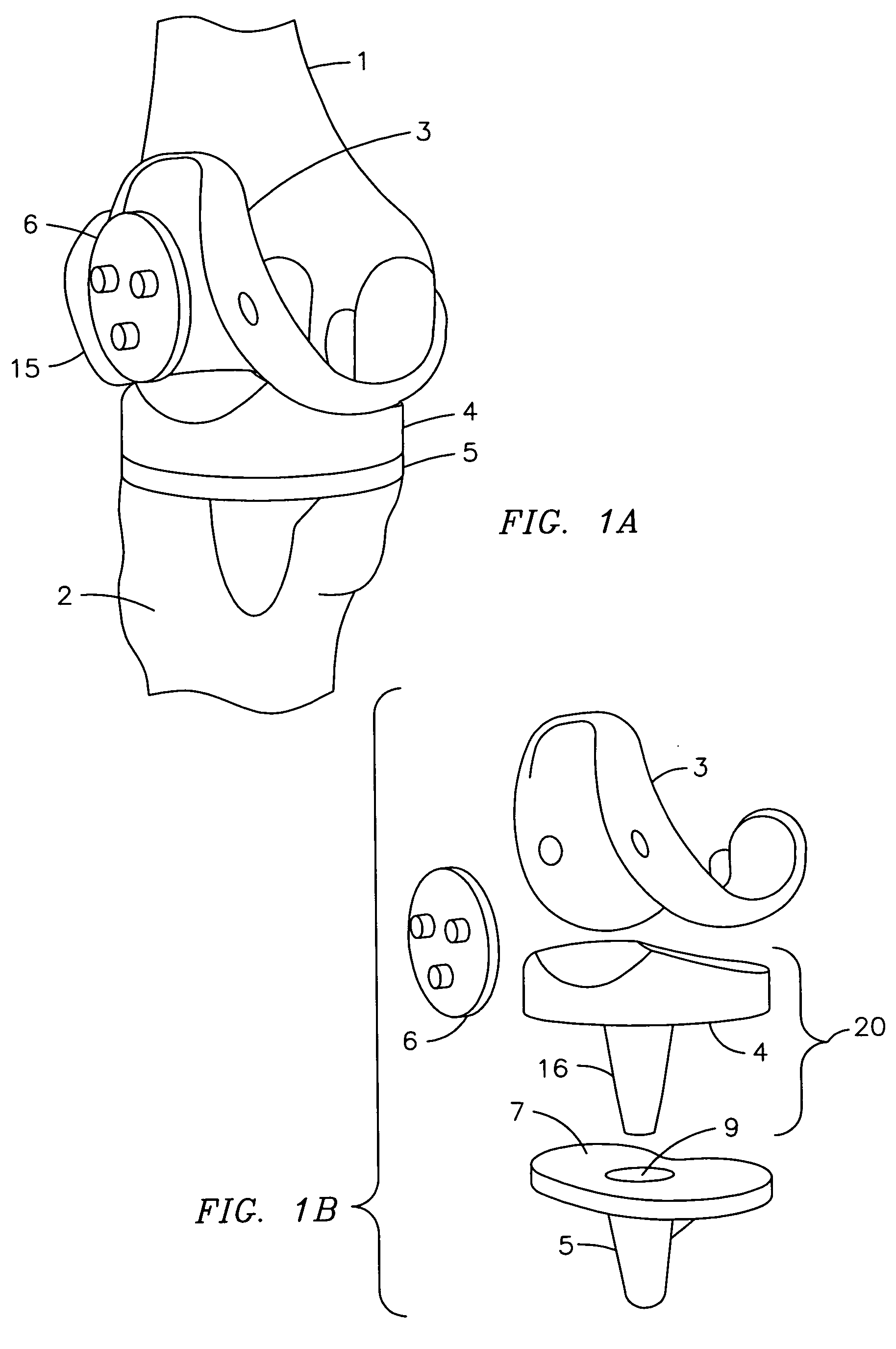
However, arthritis, trauma to the knee joint or excessive stress placed on the knee joint over time breaks down the knee joint, making movement painful, difficult and sometimes impossible.
Known as a fixed bearing design wherein the bearing is locked into the tibial component by using bone cement, the fixed bearing design led to high rates of loosening due to the amount of stress transmitted to the bone-cement or bone-prosthesis interface.
However, even with the traditional unconstrained design, the prosthesis tends to have a limited lifetime before loosening, especially on the tibial component.
This, in turn, caused surgeons to limit the total knee arthroplasty procedure to those over sixty years of age.
However, as there are a large number of individuals needing total knee arthroplasty under the age of sixty, the need for an even more unconstrained yet stable knee became of great importance.

Method used


Image

  • Knee joint prosthesis used in total knee arthroplasty
  • Knee joint prosthesis used in total knee arthroplasty
  • Knee joint prosthesis used in total knee arthroplasty

Examples


first embodiment

[0065]On the other hand, the present invention permits a longer lasting prosthetic knee having a greater range of movement by providing improved tibial components and bearings that are used in conjunction with a femoral component and patellar component for total knee arthroplasty. As shown in FIG. 2, the present invention shows a perspective view of a tibial component and tibial bearing insert of the present invention. The tibial component 5 is preferably made of a porous material so as to promote ingrowth; however, the tibial component may also be smooth as well. In addition, the tibial component base plate 7 is preferably made of a highly polished metal, although other material, such as polyethylene, may also be used. Similar to the convention tibial component 5, the tibial component 5 of the present invention includes a socket 9.

[0066]However, unlike the tibial bearing insert 20 of the prior art, the tibial bearing insert 20 of a first embodiment of the present invention includes...

third embodiment

[0076]Next, in FIGS. 15-17, varying views of the tibial component 5 and tibial bearing insert 20 of the present invention are shown, the only difference being the shape of the extension 17 being a trapezoid 13 and the central socket area 14 and track 11 being shaped and sized for acceptance of same.

[0077]In FIGS. 18 and 19, varying sectional views of a fourth embodiment of a tibial component and bearing in an anterior position of the present invention is shown. Similar to the previous embodiments of the present invention, the fourth embodiment includes an extension 17 having a predetermined shape and perimeter 18, a socket 9 having a central socket area 14 that is similar to the perimeter 18 of the extension 17, at least one retaining edge 10 covering a predetermined portion of the track 11 and a track 11 sized and shaped for movement of the extension 17. However, in the fourth embodiment, the extension 17, in this case sphere 8, is located on the tibial component 5, preferably atta...


PUM


Abstract

A knee joint prosthesis used in total knee arthroplasty having tibial components (5) and tibial bearing inserts (20) with predetermined shapes that allow for an additional degree of freedom in both an anterior-posterior direction and rotation. The tibial bearing inserts (20) include a predeterminedly-shaped extension (17), such as a sphere (8), disc (12) or trapezoid (13), that extends downwardly from the bearing (4). The tibial components (5) include a socket (9) having a corresponding predetermined shape of the extension (17) and retaining edges (10) located at a top of the socket (9) so the extension (17) may be “dropped into” the socket (9) and therein retained. In this manner, disengagement of the tibial bearing inserts (20) at extremes of anterior or posterior translation of the bearing relative to the tibial component (5) is prevented without affected the translation and rotation of the tibial component (5) and tibial bearing inserts (20).

Description

BACKGROUND OF THE INVENTION[0001]This invention relates to a knee joint prosthesis, more particularly, a knee joint prosthesis used in total knee arthroplasty having tibial bearing inserts and tibial components that provide both axial rotation and anterior-posterior rotation of the prosthetic knee as compared to the conventional fixed bearing knees.[0002]A knee joint is created when a top of the shinbone, called the tibia, and a bottom of a thighbone, called a femur,join together. A person's kneecap, orpatella, is anteriorto the tibia and femur and cartilage provides padding between the bones to assist in smooth, gliding movement of the knee joint. A synovial membrane produces a lubricant to further assist in the smooth, gliding movement of the knee joint. However, arthritis, trauma to the knee joint or excessive stress placed on the knee joint over time breaks down the knee joint, making movement painful, difficult and sometimes impossible.[0003]To help a patient regain painless mo...

Claims


Application Information

Patent Timeline
IPC IPC(8): A61F2/38
CPCA61F2/3868
Inventor STCHUR, ROBERT P.
Owner STCHUR ROBERT P
Learn More