Flash Module with Plane-Interleaved Sequential Writes to Restricted-Write Flash Chips
What is Al technical title?
Al technical title is built by PatSnap Al team. It summarizes the technical point description of the patent document.
a flash memory and write chip technology, applied in the field of flash memory solid-stated-disk systems, can solve the problems of mlc flash chips imposing additional restrictions on usage, flash is not as easy to use as a cache, and mlc flash chips may not allow pages to be written a second tim
Inactive Publication Date: 2008-02-07
SUPER TALENT TECH CORP
View PDF2 Cites 243 Cited by
Summary
Abstract
Description
Claims
Application Information
AI Technical Summary
This helps you quickly interpret patents by identifying the three key elements:
Problems solved by technology
Method used
Benefits of technology
Problems solved by technology
However, since flash memory chips are block-addressable rather than randomly-accessible, flash is not as easy to use for a cache as DRAM or SRAM.
However, MLC flash chips may impose additional restrictions on usage.
For example, a MLC flash chip may not allow pages to be written a second time before erase.
Some MLC flash chips may be even more restrictive, only allowing pages to be written in a sequence within a block, and not allowing pages to be written out-of-order.
When these stale pages are in blocks with valid pages, the wasted space is not recovered and remains.
The amount of stale pages per block varies, but can average 50%, resulting in perhaps 50% wasted space in flash memory 14 once all blocks are used.
This wasted space is undesirable, since flash memory 14 may over time eventually use all blocks, with no erased blocks available for new data.
The limitations of newer MLC flash memory may thus result in more wasted space.
Stale pages that cannot be over-written are wasted space when valid data in the same block is present.
Method used
Image
Click on the blue label to locate the original text in one second.
Reading with bidirectional positioning of images and text.
Examples
Embodiment Construction
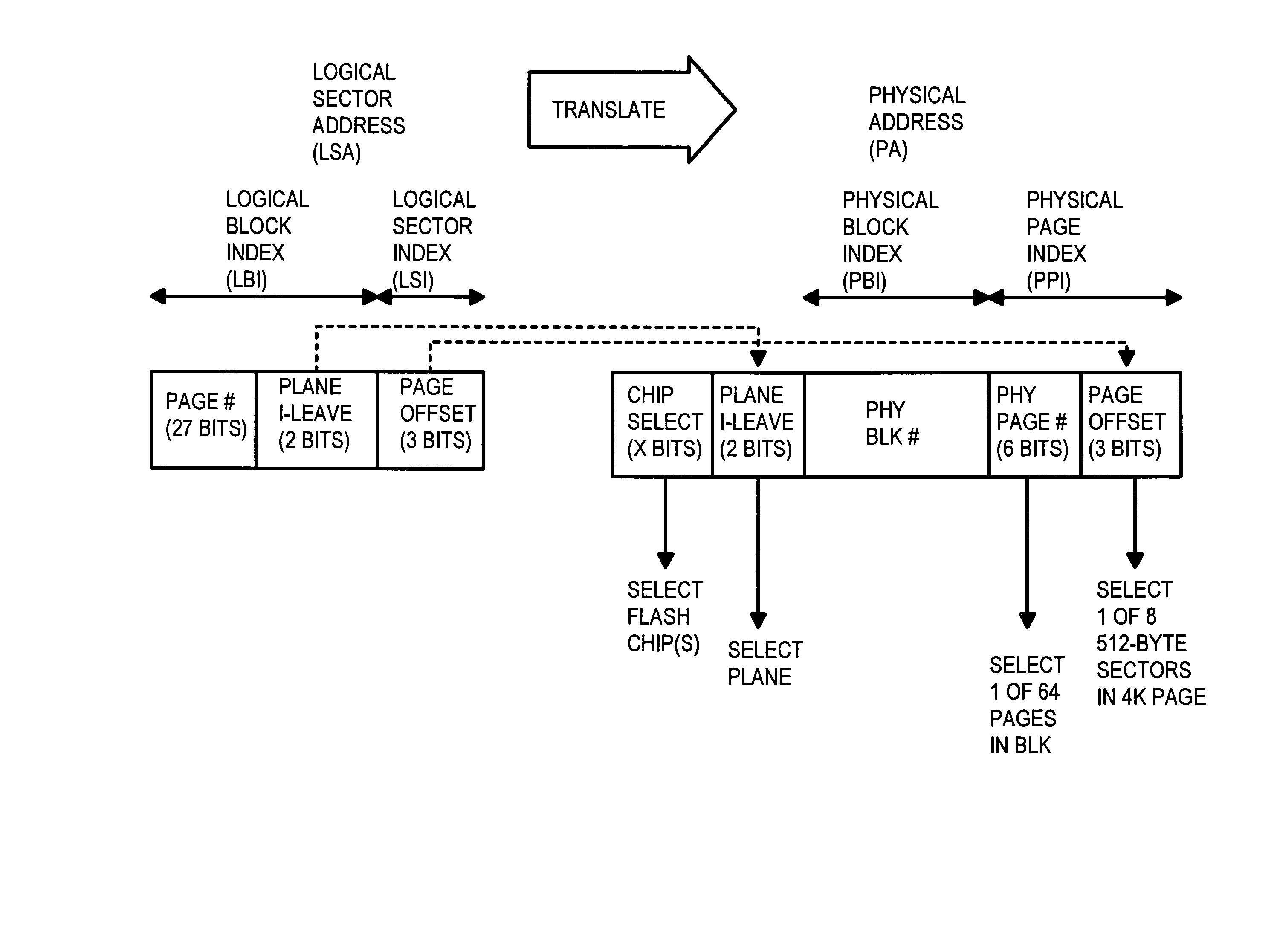
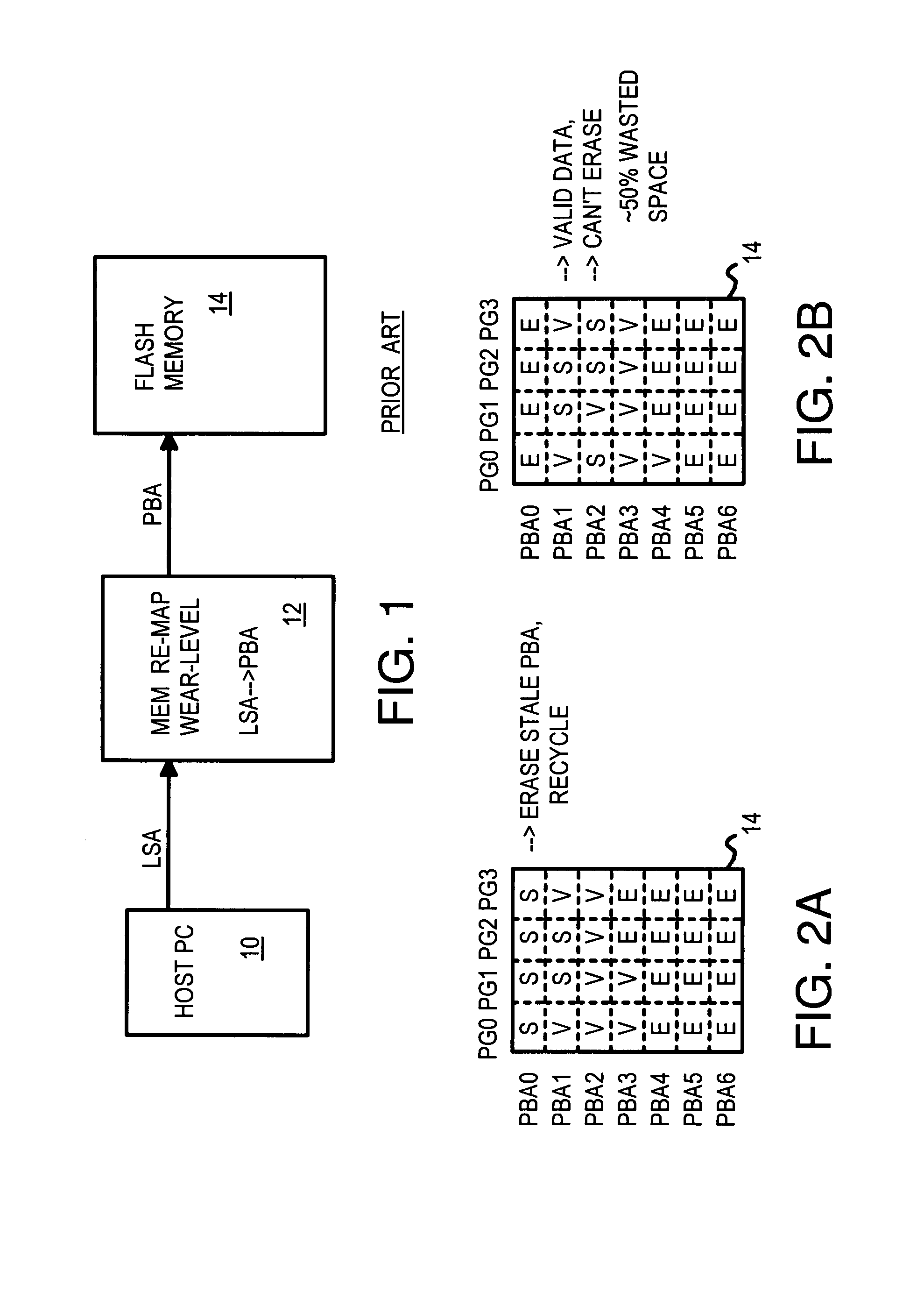
[0026] The present invention relates to an improvement in flash memory controllers. The following description is presented to enable one of ordinary skill in the art to make and use the invention as provided in the context of a particular application and its requirements. Various modifications to the preferred embodiment will be apparent to those with skill in the art, and the general principles defined herein may be applied to other embodiments. Therefore, the present invention is not intended to be limited to the particular embodiments shown and described, but is to be accorded the widest scope consistent with the principles and novel features herein disclosed.
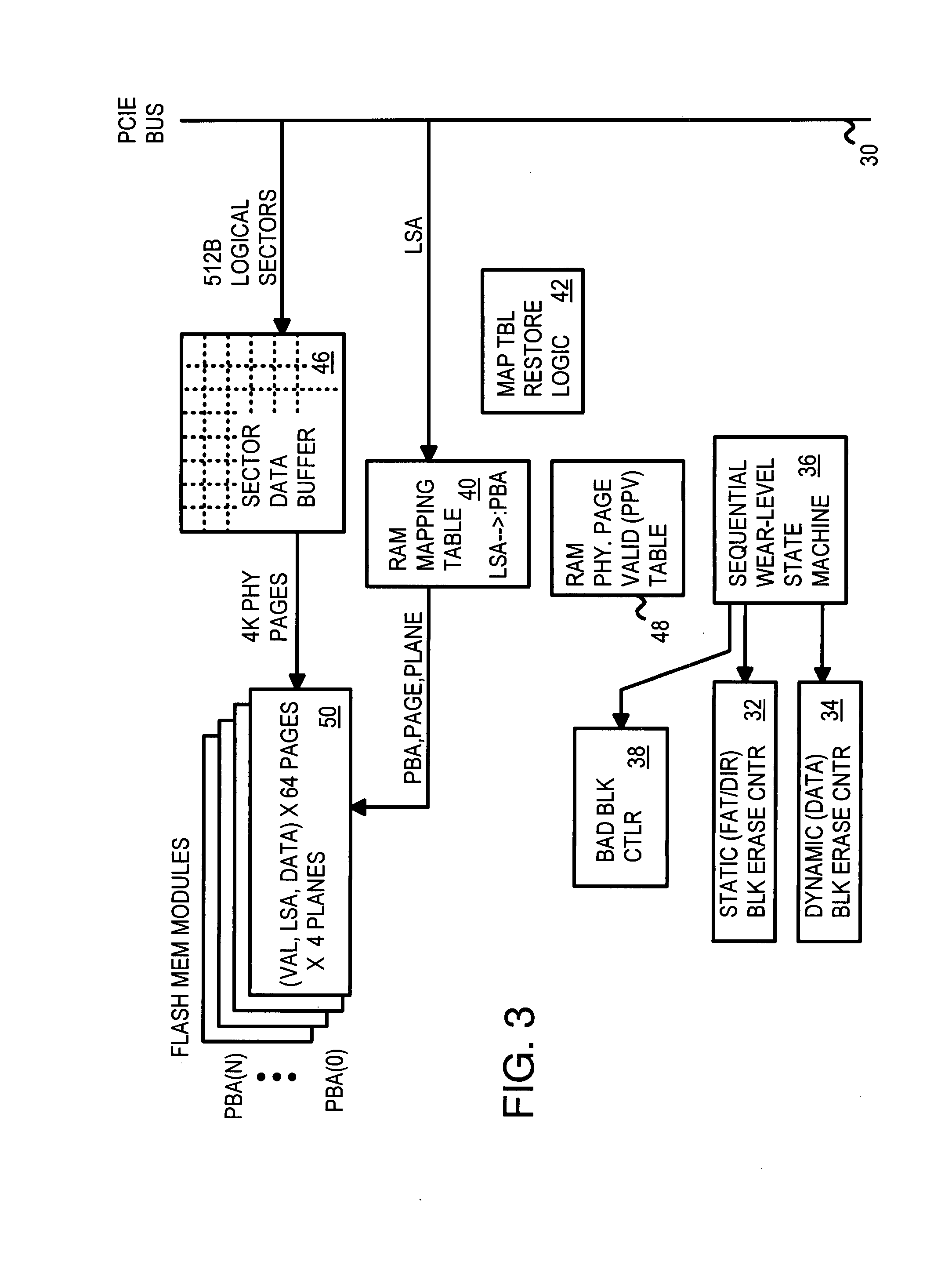
[0027]FIG. 3 is a block diagram of a flash-memory card. The flash-memory card connects to a host PC through an external I / O processor over PCIE bus 30. The flash-memory card generates packets and performs handshaking in response to commands received over PCIE bus 30.
[0028] Sector data buffer 46 stores 512-byte sectors of d...
PUM
Abstract
A flash memory controller on a PCIE bus controls flash-memory modules on a flash bus. The flash-memory modules are plane-interleaved using interleaved bits extracted from the lowest bits of the logical block index. These plane-interleave bits are split into a LSB and a MSB, with middle physical block bits between the LSB and MSB. A physical sequential address counter generates a physical block number by incrementing the plane-interleave bits before the middle physical block bits, and then relocating the MSB to above the middle physical block bits. This causes blocks to be accessed in a low-high sequence of 0, 1, 4096, 4097, 2, 3, 4098, 4099, etc. in the four planes of flash memory. A RAM physical page valid table tracks valid pages in the four planes, while a RAM mapping table stores the plane, block, and page addresses for logical sectors generated by the physical sequential address counter.
Description
RELATED APPLICATION [0001] This is a continuation-in-part (CIP) of the co-pending application for “Electronic Data Storage Medium with Fingerprint Verification Capability”, U.S. Ser. No. 11 / 624,667 filed Jan. 18, 2007, which is a divisional application of U.S. patent application Ser. No. 09 / 478,720, filed on Jan. 6, 2000, now U.S. Pat. No. 7,257,714, which has been petitioned to claim the benefit of CIP status of one of inventor's earlier U.S. patent applications for “Integrated Circuit Card with Fingerprint Verification Capability”, U.S. application Ser. No. 09 / 366,976, filed Aug. 4, 1999, now issued as U.S. Pat. No. 6,547,130, and “Flash Memory Controller for Electronic Data Flash Card” U.S. Ser. No. 11 / 466,759, filed Aug. 23, 2006, which is a CIP of “System and Method for Controlling Flash Memory”, U.S. Ser. No. 10 / 789,333, filed Feb. 26, 2004. [0002] This application is related to “Flash memory device and architecture with multi level cells”, U.S. Ser No. 10 / 800,228, filed Mar. ...
Claims
Application Information
Patent Timeline
Application Date:The date an application was filed.
Publication Date:The date a patent or application was officially published.
First Publication Date:The earliest publication date of a patent with the same application number.
Issue Date:Publication date of the patent grant document.
PCT Entry Date:The Entry date of PCT National Phase.
Estimated Expiry Date:The statutory expiry date of a patent right according to the Patent Law, and it is the longest term of protection that the patent right can achieve without the termination of the patent right due to other reasons(Term extension factor has been taken into account ).
Invalid Date:Actual expiry date is based on effective date or publication date of legal transaction data of invalid patent.
Patent Type & Authority Applications(United States)