Overlay mark

Active Publication Date: 2008-02-07
NAN YA TECH
View PDF10 Cites 26 Cited by
  • Summary
  • Abstract
  • Description
  • Claims
  • Application Information

AI Technical Summary

Problems solved by technology

In addition, the BiB overlay mark on the layer of wafer may be eroded after processes including etching, CMP or ion implant such that alignment procedure can not be performed accurately.

Method used


Image

  • Overlay mark
  • Overlay mark
  • Overlay mark

Examples


Embodiment Construction

[0025]Referring now to the drawings, and more particular to FIGS. 4-5B, there are shown exemplary embodiments of the overlay mark configuration according to the present invention.

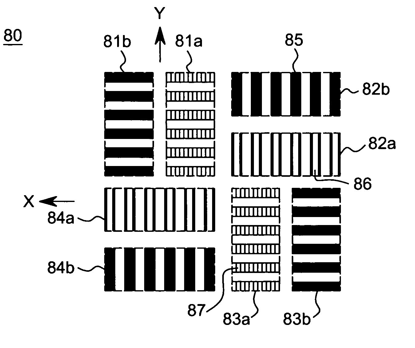
[0026]As indicated in FIG. 4, the embodiment discloses an AIM configuration with improved overlay mark. Similar to that disclosed in and described for FIG. 3C, this overlay configuration includes four aligned rectangular regions 81a, 82a, 83a and 84a, and four rectangular regions 81b, 82b, 83b and 84b. Each rectangular region has plurality of first pattern element 85 distributed evenly in each rectangular region. In addition, as indicated in FIG. 4, both the second aligned rectangular region 82a and the fourth aligned rectangular region 84a on x-orientation have plurality of second pattern element 86 distributed evenly therein; both the first aligned rectangular region 81a and the third aligned rectangular region 83a on y-orientation have plurality of third pattern element 87 distributed evenly therein. Whe...


PUM


Abstract

An overlay mark formed on a photomask, comprising a first rectangular region, a second rectangular region, a third rectangular region, and a fourth rectangular region, each rectangular region having the same pattern configuration, a longer side of the first rectangular region and a longer side of the third rectangular region being parallel to each other, and the first and third rectangular regions have the same first pattern configuration having a first pattern element, a longer side of the second rectangular region and a longer side of the fourth rectangular region being parallel to each other, and the second and fourth rectangular regions have the same second pattern configuration having a second pattern element, the longer side of the first rectangular region being perpendicular to the longer side of the second rectangular region; wherein, the first pattern element is different from the second pattern element for allowing the second pattern configuration be chosen to align when the first pattern configuration on the substrate was damaged during process.

Description

FIELD OF INVENTION[0001]The present invention generally relates to an overlay mark, and more particularly, to an overlay mark used for overlaying alignment between photomasks during integrated circuit (IC) process.BACKGROUND OF THE INVENTION[0002]Photolithography is one of the most critical steps in IC manufacturing process. The quantity of photomask and lithography needed in the process indicates the integration complication of the IC. The improvement of lithography determines whether the IC can have a smaller feature dimension than previous generation. Exposure of photo-resist is one of the critical steps in lithography process due to its accuracy requirement. As mentioned above, the IC manufacturing process involves typically more than ten photomasks of different patterns, the alignment between the photomasks critically determines the quality of patterns transferred to the target layer and the final performance of the IC.[0003]As well known in the arts, the step and repeat projec...

Claims


Application Information

Patent Timeline
IPC IPC(8): G06F17/50
CPCG03F1/14G03F9/7076G03F7/70683G03F7/70633G03F1/42
Inventor CHIU, CHUI-FUWU, WEN-BIN
Owner NAN YA TECH
Why Eureka
Try Eureka