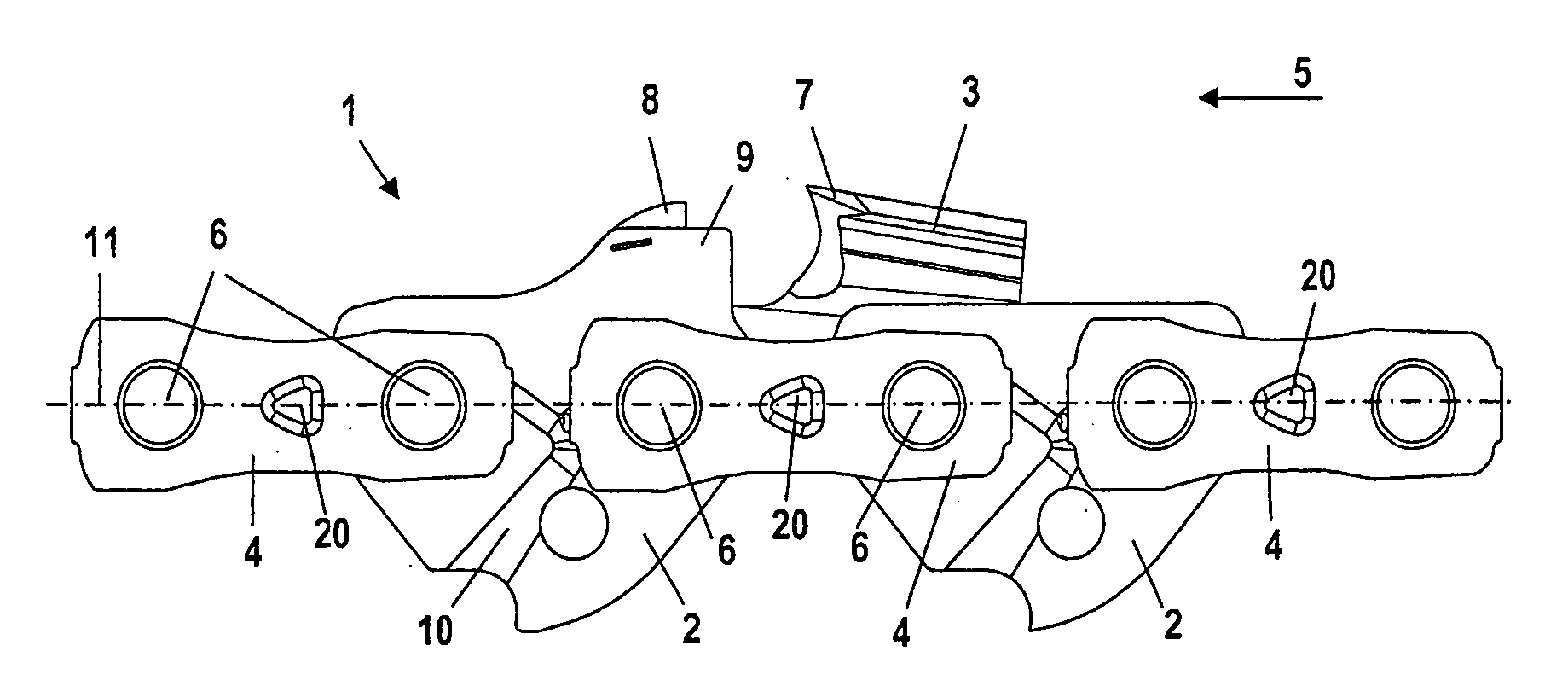
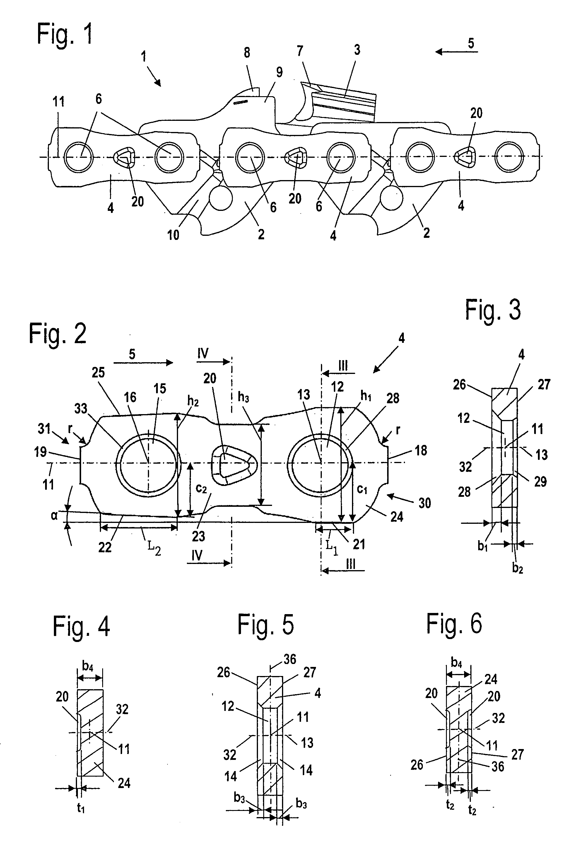
[0007]It can, however, be provided that the connecting link is configured to be mirror symmetrical to a plane containing the longitudinal center axis and the axes of the rivet openings. Accordingly, the connecting link has a contour on the upper end which likewise has running surfaces. In a connecting link wherein the elevation in the region of the trailing rivet opening is less than the elevation in the region of the leading rivet opening, a lower elevation of the connecting link results in the region of the trailing rivet opening because of the mirror symmetrical configuration. For a connecting link which is arranged next to a
cutting link, the
chip channel is increased by the reduction of the elevation of the connecting link at the trailing rivet opening. The
chip removal is improved.
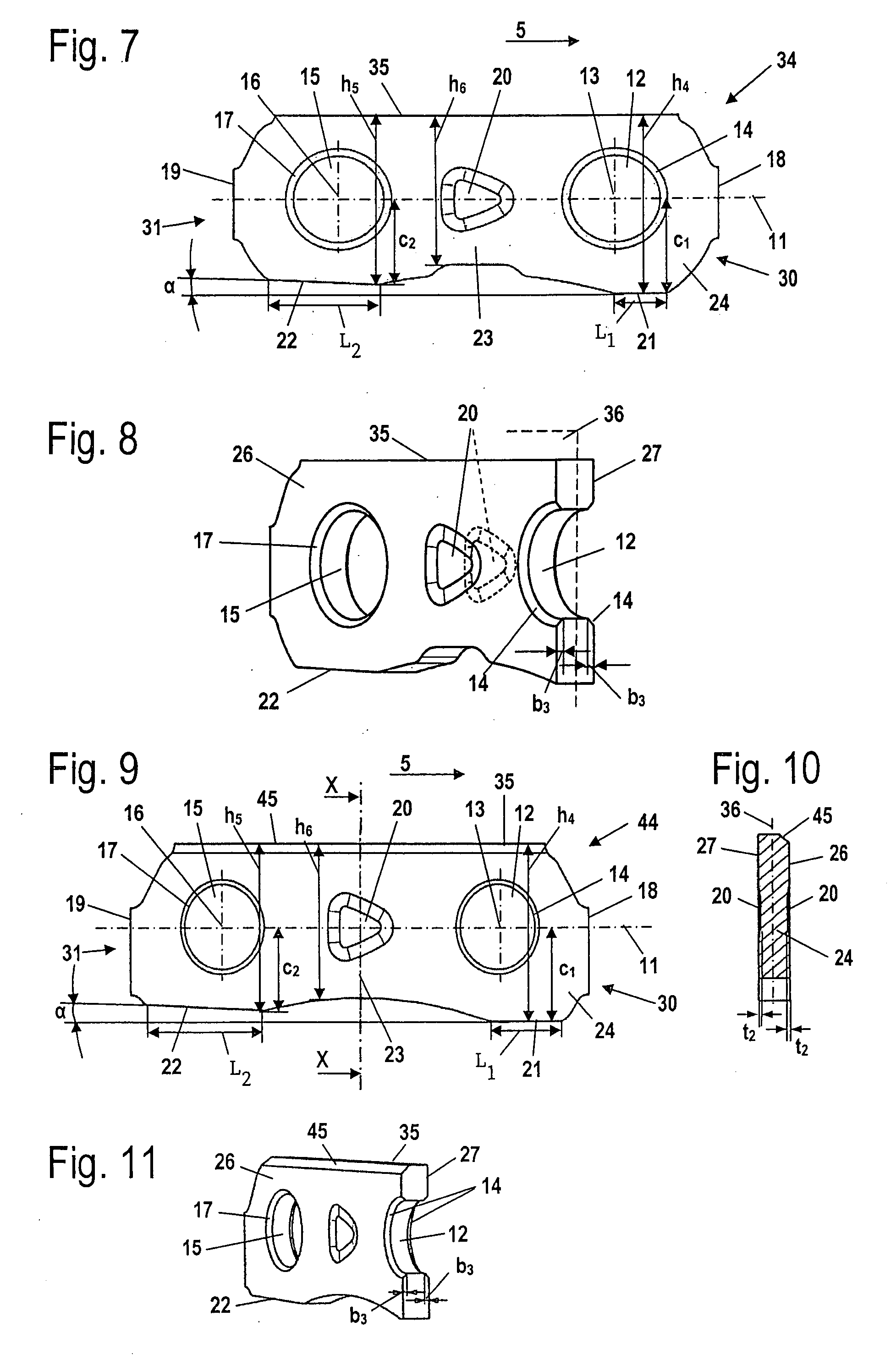
[0008]Because of the mirror symmetrical configuration, the connecting link can be arranged on both longitudinal sides of the saw chain by a rotation of 180° about the longitudinal center axis. The symmetrical configuration leads to a uniform loading of the connecting link because, with tension stresses (that is, stresses in the running direction of the saw chain or in the longitudinal direction of the saw chain), the same stresses arise above and below the symmetry plane. In this way, bending forces are avoided. Advantageously, the rivet opening has a
countersink on an outer side of the connecting link and a bevel on an opposite-
lying inner side. The width of the
countersink, which is measured parallel to the axis of the rivet opening, is greater than the width of the bevel. The head of a rivet is arranged in the
countersink. The bevel ensures only the deburring of the rivet opening on the opposite-
lying inner side of the connecting link. With the mirror symmetrical configuration of the connecting link, the outer side of the connecting link faces outwardly, independently of on which longitudinal side of the saw chain the connecting link is mounted. In this way, the countersink can be configured to be comparatively large whereas the width of the bevel can be very narrow. However, bevels of the same width can be provided on both longitudinal sides. In this way, the connecting link can be configured to be symmetrical to a plane containing the longitudinal center axis and
lying in the plane of the connecting link as well as be symmetrical to a second plane which contains the longitudinal center axis and the axes of the rivet openings.
[0009]Advantageously, the connecting link has a smaller elevation in the region of the rivet opening leading in the running direction than in the region of the trailing rivet opening with this elevation being measured perpendicularly to the axis of the rivet opening and to the longitudinal center axis. In this way, the vibrations of the saw chain developing during operation are reduced. In the region lying between the rivet openings, the connecting link has especially an elevation which is less than the elevation in the region of the leading rivet opening and less than the elevation in the region of the trailing rivet opening. The reduced elevation in the region between the rivet openings permits small direction-changing radii of the saw chain. The strength is reduced because of the lesser elevation and this can be countered by the arrangement of an impression. The connecting link has a forward running surface next to the leading rivet opening and a rearward running surface next to the trailing rivet opening. The length of the rearward running surface is greater than the length of the forward running surface. During operation, greater forces act at the rearward running surface. The wear-caused
material removal at the rearward running surface is reduced because of the lengthening of the rearward running surface. The rearward running surface is advantageously so measured with respect to the forward running surface that the wear-caused
material removal is approximately the same at both running surfaces during operation.
[0010]It is practical that the forward-running surface runs parallel to the longitudinal center axis. The forward running surface and the rearward running surface conjointly define an angle. The angle preferably opens rearwardly referred to the running direction. The angle between the-forward and rearward running surfaces reduces the vibrations of the saw chain occurring during operation because a connecting link, which is so configured, permits a slight tilting of a
cutting link when the
cutting link comes into contact with the workpiece to be
cut. The cutting link is arranged on the opposite-lying side of the connecting link. Advantageously, the angle is 1° to 5°. Low vibrations result especially at an angle of 2° to 3°. To permit a tilting during operation, it is furthermore provided that the maximum spacing of the forward running surface to the longitudinal center axis is greater than the maximum distance of the rearward running surface to the longitudinal center axis.
[0012]Advantageously, the connecting link has at least one depression on the base body. The depression on the base body defines no functional region of the connecting link and can therefore be configured to be unsymmetrical. The depression is especially so configured that it ensures the orientation of the connecting link in the pregiven direction. Advantageously, the depression is arranged in a region between the rivet openings and is configured as an impression in whose region the material of the connecting link is compressed. The impression between the rivet openings can be introduced simply into the connecting link. During the pressing process, the material in the region between the rivet openings is deformed and compressed. This leads to an increased strength in this region.
[0013]Advantageously, the impression is intersected by a plane which contains the axes of the rivet openings and the longitudinal center or middle axis. The impression is thereby arranged at the elevation of the rivet openings, that is, in a region subjected to intense
mechanical load. Advantageously, the impression is in the form of an arrow head which points in the running direction of the connecting link. The connecting links are configured differently in the region of the leading rivet opening and in the region of the trailing rivet opening. The connecting link must therefore be assembled in the correct position. With the configuration of the impression in the form of an arrow head, the correct orientation of the connecting link is shown in a simple manner without additional means being necessary. In this way, the
assembly is simplified. Also, for an exchange of the connecting link by the operator, a position-correct installation is ensured because of the impression. On each side of the base body, an impression is arranged and both impressions point in the same direction. In this way, in every built-in position, an impression points in the running direction so that the operator can easily control the position-correct installation.


