
Perforating system comprising an energetic material

a perforating system and energy material technology, applied in the direction of explosive charges, fluid removal, borehole/well accessories, etc., can solve the problems of affecting the hydrocarbon production of particular wellbores, affecting the quantity of hydrocarbons produced from the particular wellbore, and the associated components of many fragments

Active Publication Date: 2008-02-14
BAKER HUGHES INC
View PDF35 Cites 33 Cited by
  • Summary
  • Abstract
  • Description
  • Claims
  • Application Information

AI Technical Summary

Benefits of technology

[0016] The present invention described herein, therefore, is well adapted to carry out the objects and attain the ends and advantages mentioned, as well as others inherent therein. While a presently preferred embodiment of the invention has been given for purposes of disclosure, numerous changes exist in the details of procedures for accomplishing the desired results. For example, the invention described herein is applicable to any shaped charge phasing as well as any density of shaped charge. Moreover, the invention can be utilized with any size of perforating gun. It also should be pointed out that the apparatus herein disclosed is not limited to a shaped charge for use with a perforating gun, but can also include any type of ballistics shaped charge —such as those shaped charges used in weaponry and ordinance related technology. These and other similar modifications will readily suggest themselves to those skilled in the art, and are intended to be encompassed within the spirit of the present invention disclosed herein and the scope of the appended claims.

Problems solved by technology

Due to the high force caused by the explosive, the shaped charge and its associated components often shatter into many fragments, some that can exit the perforating gun into the fluids within the wellbore.
These fragments can clog as well as damage devices such as chokes and manifolds thereby restricting the flow of fluids through these devices and possibly hampering the amount of hydrocarbons produced from the particular wellbore.

Method used


Image

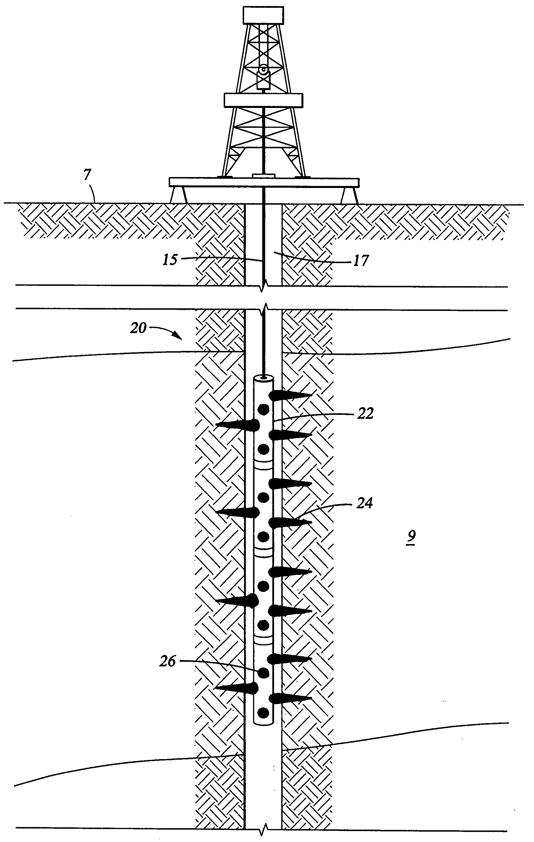
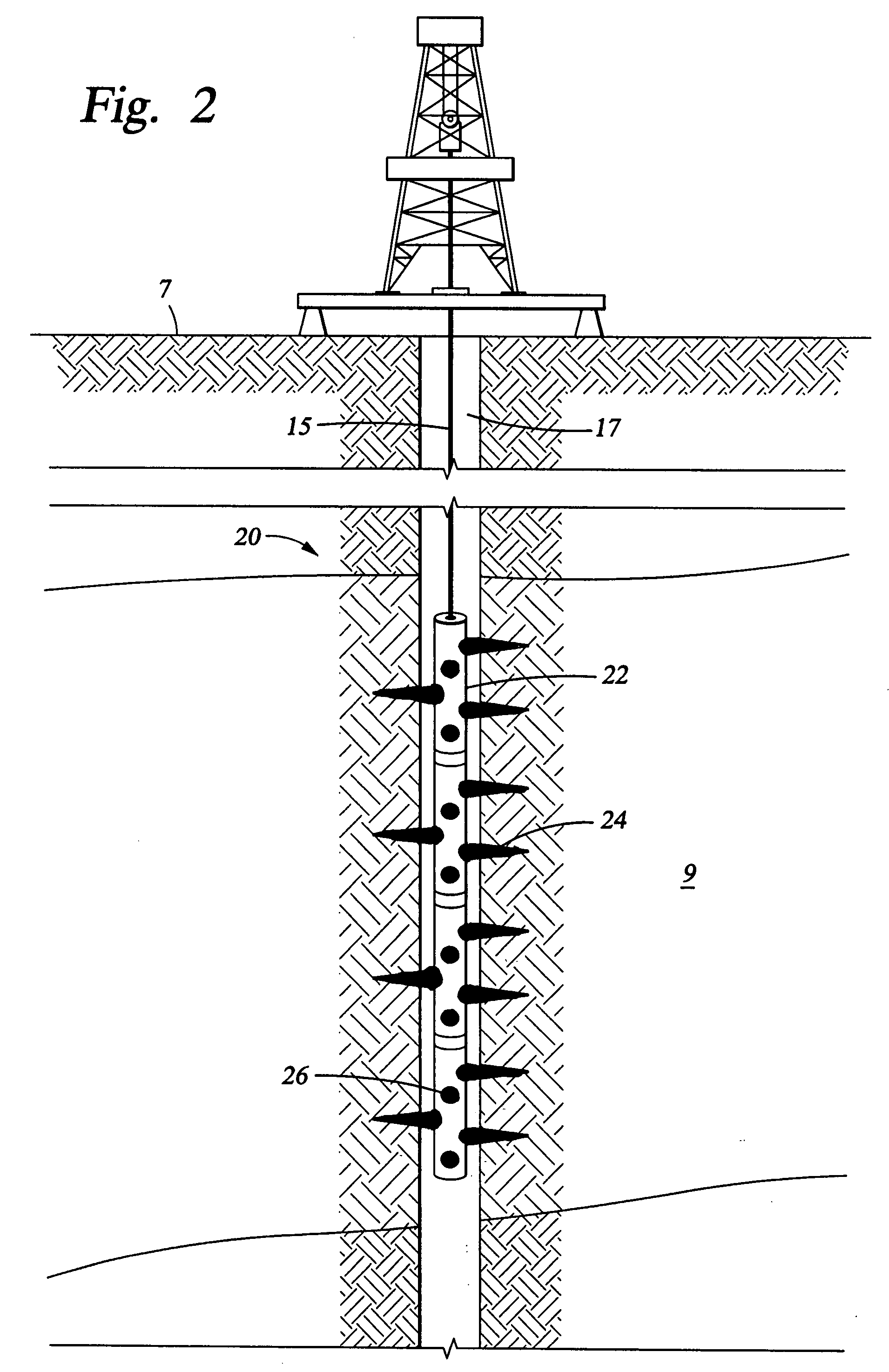
  • Perforating system comprising an energetic material
  • Perforating system comprising an energetic material
  • Perforating system comprising an energetic material

Examples


Embodiment Construction

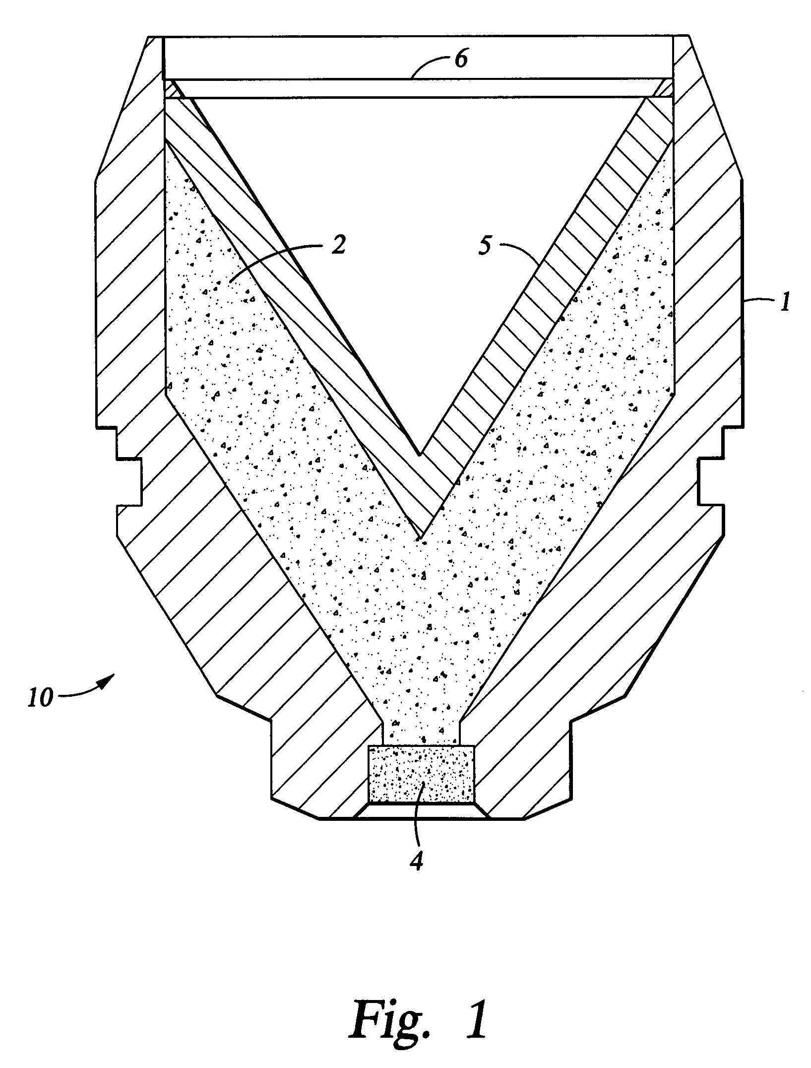
[0011] With reference to the drawings herein, FIG. 1 depicts a cross sectional view of one embodiment of the present invention in a side aspect. As shown, this embodiment is a shaped charge 10 comprising a charge case 1, a liner 5, explosive 2, an initiator 4, and an optional covering 6. In one embodiment, the material for the charge case 1 and the liner 5 could comprise a reactive energetic material that changes its state from a solid material to a substantially vapor phase composition. The reaction of the energetic material (i.e. its change of state) can be induced subsequent to activation of the shaped charge 10. Initiation of the energetic material reaction may be accomplished by the activation of the shaped charge 10, or by a separate initiating event. It should however occur subsequent to the activation of shaped charge 10. It should be pointed out that the energetic material could have its change of state simultaneous to activation of the shaped charge 10 or at some time afte...


PUM

PropertyMeasurementUnit
perforating lengthaaaaaaaaaa
chargeaaaaaaaaaa
velocityaaaaaaaaaa

Abstract

A perforating system, including a shaped charge assembly comprising a charge case, a liner, and a main body of explosive. The material of the perforating system components, including the gun body, the charge case and the liner may be comprised of an energetic material that conflagrates upon detonation of the shaped charge. The material may be an oxidizer, tungsten, cement particles, rubber compounds, compound fibers, KEVLAR®, steel, steel alloys, zinc, and combinations thereof.

Description

RELATED APPLICATIONS [0001] This application claims priority from co-pending U.S. Provisional Application No. 60 / 809,004, filed May 26, 2006, the full disclosure of which is hereby incorporated by reference herein.BACKGROUND OF THE INVENTION [0002] 1. Field of the Invention [0003] The invention relates generally to the field of oil and gas production. More specifically, the present invention relates to a shaped charge system and / or gun body. Yet more specifically, the present invention relates to a perforating gun system that after detonation of its associated shaped charges minimizes wellbore gun fragments produced during well perforations. Also the gun system could be designed to disappear upon initiation, doing away with retrieval operations of hardware left downhole. [0004] 2. Description of Related Art [0005] Perforating systems are used for the purpose, among others, of making hydraulic communication passages, called perforations, in wellbores drilled through earth formations ...

Claims


Application Information

Patent Timeline
Patent Type & Authority Applications(United States)
IPC IPC(8): E21B43/117F42B3/00
CPCE21B43/117F42B1/032F42B1/02E21B43/116F42B3/08F42B3/22
Inventor EVANS, RANDY L.HILL, FREEMAN L.HETZ, AVIGDORHONEKAMP, JEFFREY
Owner BAKER HUGHES INC
Learn More