
Cockpit oxygen mask

a technology of oxygen mask and cockpit, which is applied in the field of cockpit oxygen mask, can solve the problems of large quantity of oxygen which is not used and consumed, and achieve the effect of adequate oxygen supply and as little as possible oxygen consumption

Active Publication Date: 2008-02-14
BE AEROSPACE SYST
View PDF9 Cites 8 Cited by
  • Summary
  • Abstract
  • Description
  • Claims
  • Application Information

AI Technical Summary

Benefits of technology

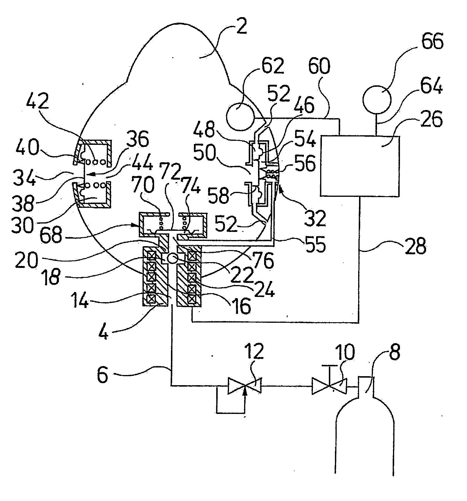
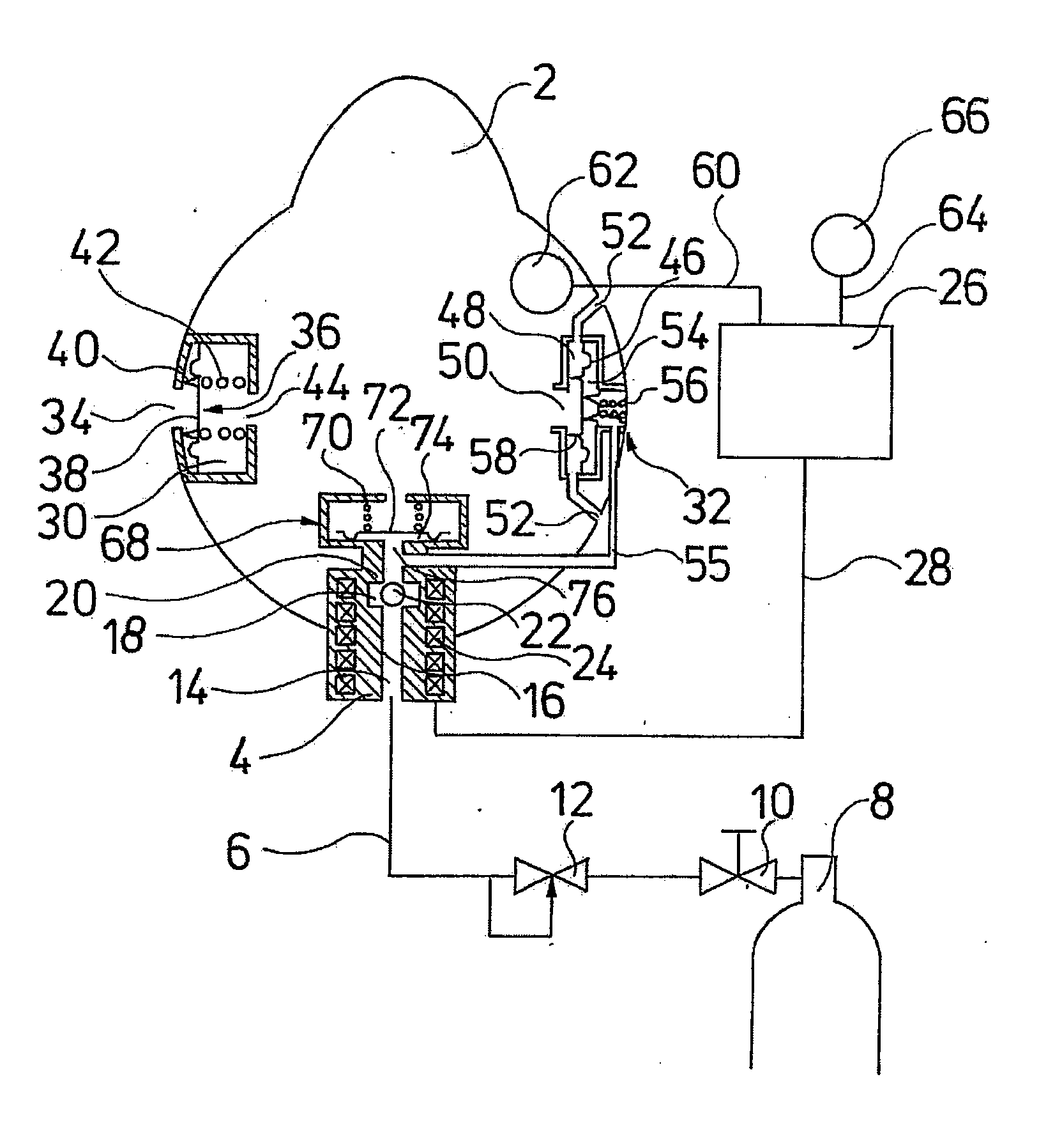
[0008] A magnet valve designed in such a manner is described in DE 199 22 414 C1. Preferably, with this magnet valve, a magnetic field running parallel to the wall is produced in a wall limiting the flow path by way of a coil subjected to current. An discontinuous location in the form of a groove is provided in the wall, which leads to a concentration of the magnetic field, in a manner such that the magnetic field extends further into the flow path in the region of the discontinuous location, and thus may affect the valve body arranged in the throughflow path, and may move it away from the valve seat. Furthermore, the magnet valve is designed such that the fluid pressure prevailing at the entry side of the valve, presses the valve body against the valve seat when the wall of the throughflow path is not magnetized, and in this manner automatically closes the throughflow path. The magnet valve advantageously has a small constructional size and a low weight.
[0020] Preferably, the oxygen inhalation valve comprises two exits. Thereby, a first exit opens into the mask body. This first exit accordingly serves for the oxygen supply of the user of the cockpit oxygen mask. A second exit is conductingly connected to the exhalation valve via an overflow channel. The fluidic coupling from the oxygen inhalation valve and the exhalation valve is effected via the overflow channel. For this, the overflow channel is preferably connected to the exhalation valve such that with an opened oxygen inhalation valve, a part flow of the oxygen flowing through the oxygen inhalation valve, flows into the exhalation valve via the overflow channel and there, presses a sealing body which closes a flow path leading from the inside of the mask body to the outside of the cockpit oxygen mask, against a valve seat in a closing manner, so that no oxygen may get lost via the overflow channel.

Problems solved by technology

With the cockpit oxygen masks known until now, the sluggish regulation (closed-loop control) behavior of the mechanically designed pressure regulator leads to a relatively large quantity of oxygen which is not used, being consumed, since the pressure regulation valve of the pressure regulator may only meter the oxygen quantity led into the cockpit oxygen mask in an inadequate manner, and only reacts with a delay to the requirement situation.

Method used


Image

  • Cockpit oxygen mask
  • Cockpit oxygen mask

Examples


Embodiment Construction

[0025] A cockpit oxygen mask with a mask body 2 is represented in a greatly simplified manner in the Figure. The mask body 2 comprises an oxygen inhalation valve 4 with which the oxygen supply into the inner space of the mask body 2 may be controlled. The oxygen inhalation valve 4 may be integrated into the mask body 2 or be arranged upstream of this, for example via a breathing bag which is not represented. The oxygen inhalation valve 4 is conductingly connected to an oxygen storer 8 via a supply conduit 6, wherein in the known manner, a shut-off valve 10 as well as a pressure reducer 12 are connected downstream of the oxygen storer 8 in the outflow direction. The oxygen pressure prevailing in the oxygen storer 8 and which may be more than 100 bar, is reduced by the pressure reducer 12 to an average pressure of about 2 to 3 bar.

[0026] The oxygen inhalation valve 4 is designed as an electrically actuatable ball-seat valve. It comprises a throughflow path 14 which is limited by a ma...


PUM


Abstract

A cockpit oxygen mask comprises a mask body, an oxygen inhalation valve, a mixed air inhalation valve, an exhalation valve as well as with a control device. At least the oxygen inhalation valve is signal-connected to the control device. The oxygen inhalation valve is designed as an electromagnetically actuatable valve, and comprises at least one throughflow path which may be closed by a magnetically movable valve body, wherein the throughflow path is limited by a magnetizable wall, and wherein the wall comprises at least one discontinuous location which deforms a magnetic field produced in the wall.

Description

BACKGROUND OF THE INVENTION [0001] The invention relates to a cockpit oxygen mask with the features specified in the introductory part of claim 1. [0002] With the oxygen supply systems for cockpit crews used in aircraft, for reasons of weight and space, one strives to keep the quantity or oxygen which is brought along in the aircraft as small as possible. Thereby however, one should ensure an adequate oxygen supply of the cockpit crew. This demands an as efficient as possible utilization of the oxygen which is carried on board. Oxygen losses must be avoided. [0003] In this context, cockpit oxygen masks and in particular their pressure regulators are of significance. With the cockpit oxygen masks known until now, the sluggish regulation (closed-loop control) behavior of the mechanically designed pressure regulator leads to a relatively large quantity of oxygen which is not used, being consumed, since the pressure regulation valve of the pressure regulator may only meter the oxygen qu...

Claims


Application Information

Patent Timeline
Patent Type & Authority Applications(United States)
IPC IPC(8): A62B18/02
CPCA62B7/12A62B18/10A62B9/022A61M16/20
Inventor RITTNER, WOLFGANGMECKES, RUDIGER
Owner BE AEROSPACE SYST
Learn More