Fluid contact chamber

a contact chamber and flue gas technology, applied in water supply installation, water/sewage treatment by oxidation, functional valve types, etc., can solve the problems of high energy input requirements, increased chamber size and complexity, and increased residence time, etc., to achieve good contact time and mixing

Inactive Publication Date: 2008-02-14
CONRAD WAYNE E +3
View PDF22 Cites 10 Cited by
  • Summary
  • Abstract
  • Description
  • Claims
  • Application Information

AI Technical Summary

Benefits of technology

[0003] A fluid contact chamber has been invented which allows good contact time an

Problems solved by technology

However, the provision of sufficient residence time and mixing in such contactors creates various drawbacks such as the requ

Method used


Image

  • Fluid contact chamber
  • Fluid contact chamber
  • Fluid contact chamber

Examples


Embodiment Construction

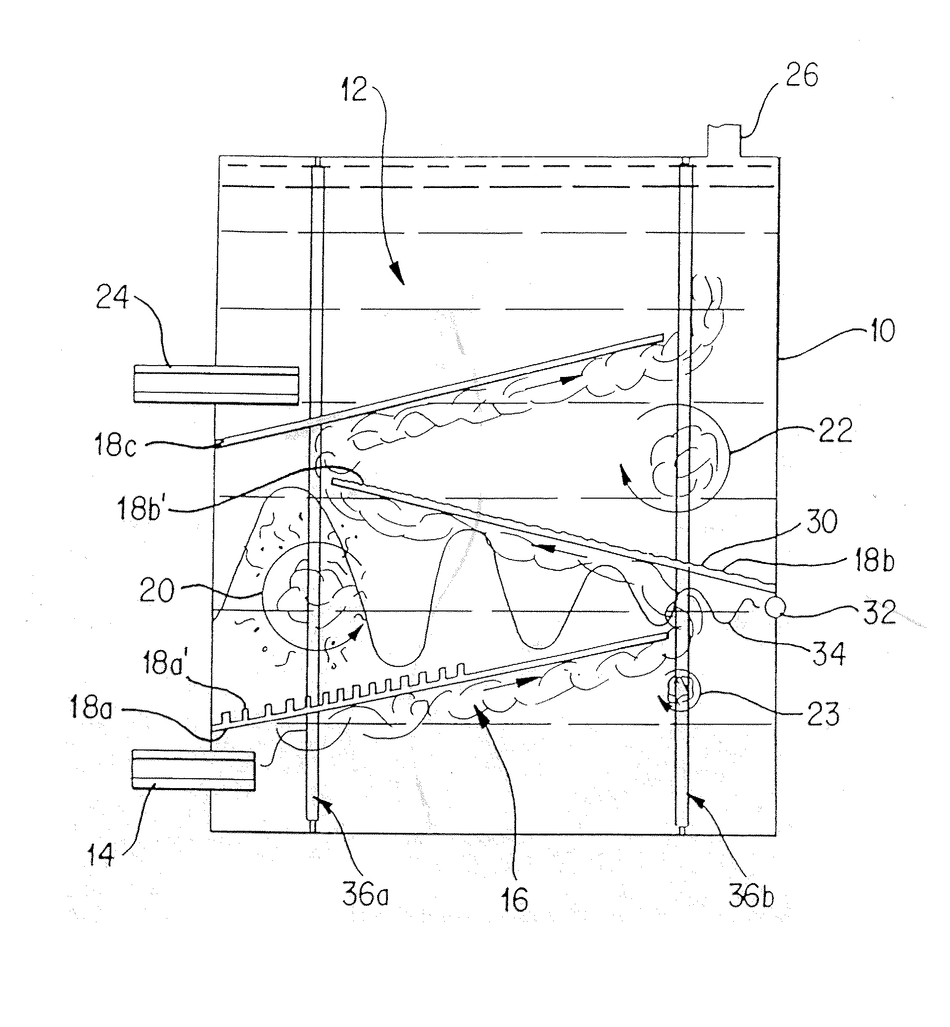
[0005] A fluid contact chamber is provided which acts to mix fluids and allow reaction thereof, if desired. The chamber comprises a container for a first fluid and an inlet for introduction of a second fluid to the container. The second fluid is caused to flow through the first fluid by any suitable means such as, for example, by application of pressure or by differential density. The chamber further comprises a means for directing the flow of the second fluid such that a deviation in the flow, termed an eddy, is created which leads to the formation of a vortex.

[0006] Vortex action causes the second fluid to be dispersed and mixed within the first fluid. In addition, the concentric flow pattern of the vortex traps the second fluid within the first fluid to increase the residence time of the second fluid in the first fluid.

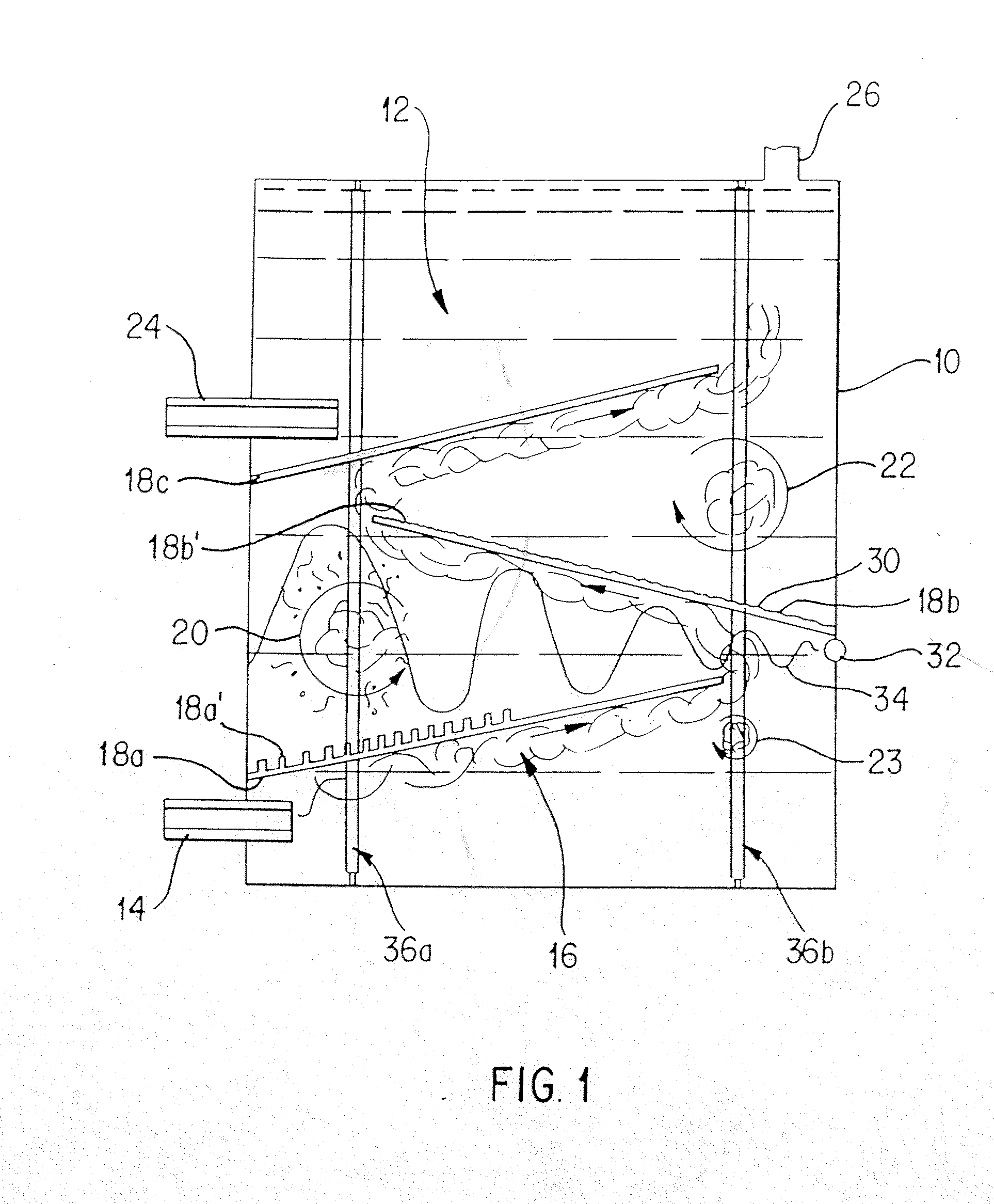
[0007] The means for directing the flow of the second fluid can be of any suitable form. For example, the means can comprise a pipe arrangement having a configur...


PUM

PropertyMeasurementUnit
Fractionaaaaaaaaaa
Timeaaaaaaaaaa
Angleaaaaaaaaaa

Abstract

A fluid contactor is taught for mixing and reacting of fluids. Mixing is enhanced by providing a suitable residence time and suitable surface area contact by forming eddy flow within the fluid and thereby the formation of vortexes. Such a contactor does not require the use of mechanical mixers. The contact chamber of the present invention can enhance chemical modification by use of chemical modifiers such as ultraviolet lamps, by allowing the positioning of such modifiers adjacent the vortexes.

Description

FIELD OF THE INVENTION [0001] This invention is directed to a fluid contact chamber and, in particular, an fluid contact chamber for mixing and reacting fluids. BACKGROUND OF THE INVENTION [0002] Fluid contactors, such as those used in the mixing and transfer of gases into liquids, are known which provide suitable results by allowing sufficient time and surface area for contact between the fluids. However, the provision of sufficient residence time and mixing in such contactors creates various drawbacks such as the requirement for high energy inputs to effect mixing and / or increased chamber size and complexity to increase the residence time. SUMMARY OF THE INVENTION [0003] A fluid contact chamber has been invented which allows good contact time and mixing by use of turbulent flow, while maintaining a compact and simple chamber. [0004] According to a broad aspect of the present invention there is provided a fluid contact chamber comprising a container for a first fluid, an inlet for ...

Claims


Application Information

Patent Timeline
IPC IPC(8): F15C1/18B01F3/04B01F5/06B01J10/00B01J19/00B01J19/10C02F1/32C02F1/36C02F1/78
CPCB01F3/0446B01F5/0617B01F5/0413B01F5/0603B01F5/0606B01J10/007B01J19/006B01J19/10B01J2219/0077C02F1/006C02F1/32C02F1/36C02F1/78C02F2201/3228C02F2301/024C02F2301/026B01F3/0451Y10T137/785Y10T137/2087Y10T137/0329Y10T137/2109B01F23/23231B01F23/232B01F25/421B01F25/312B01F25/4231B01F25/43151B01F23/2326
Inventor CONRAD, WAYNE E.CONRAD, HELMUT GERHARDPHILLIPS, RICHARD STANLEYPHILLIPS, ANDREW RICHARD HENRY
Owner CONRAD WAYNE E
Why Eureka
Try Eureka