Fork with integrated braking system

Inactive Publication Date: 2008-02-14
WHITE PHILIP G & ANNA DOPICO AS TRUSTEES OF +1
View PDF23 Cites 50 Cited by
  • Summary
  • Abstract
  • Description
  • Claims
  • Application Information

AI Technical Summary

Benefits of technology

[0019] The present invention also envisions the use of the chain stays and the seat stays as portions of structure into which a brake assembly can be integrated to reduce drag. The invention provides bicycle chain stays and seat stays in which the braking system is integrated into the chain stays or seat stays to allow the braking system to at least partially rest within the structure of the chain stays when the brakes are not engaged. The brake system may be provided in recesses provided in the middle, at the top or at the bottom of the chain the recess. These recesses allow the braking mechanism to be substantially hidden from airflow so as to reduce drag. When the braking system is fitted within the recesses of the chain stay, the chain stays can be designed in an aerodynamic fashion to reduce drag without the worry of the braking mechanism obstructing the airflow. The chain stay can therefore be designed to have an aerodynamic shape since when the brakes are not engaged they would fit at least partially

Problems solved by technology

In such known braking system configurations, the components of the braking system protrude beyond the envelope of

Method used


Image

  • Fork with integrated braking system
  • Fork with integrated braking system
  • Fork with integrated braking system

Examples


first embodiment

[0057] Reference is made to FIG. 31 which is a side view of a bicycle 109 in accordance with the invention. The bicycle 109 has a frame 110 comprising a head tube 120, a top tube 130, a down tube 140 and a seat tube 150. Each of these tubes are connected end-to-end to one another and form substantially a closed main frame loop A seat post 173 is supported by an upper end of the seat tube 150 and carries a seat 175.

[0058] A front fork 9 is pivotably coupled to the head tube 120 by extending through the head tube. The front fork 9 has a steerer tube 15 which extends upwardly to be journalled inside the head tube 120 of the bicycle frame and pivotably mount the front fork 9 to the frame for pivoting about a pivot axis 121. The fork 9 carries at an upper end of the steerer tube 15 handlebars 190. The fork 9 has a fork crown 11 which splits into a pair of fork legs (also referred to as fork arms) supporting the front wheel 178. A pair of seat stays 165 and chain stays 167 extend rearward...

second embodiment

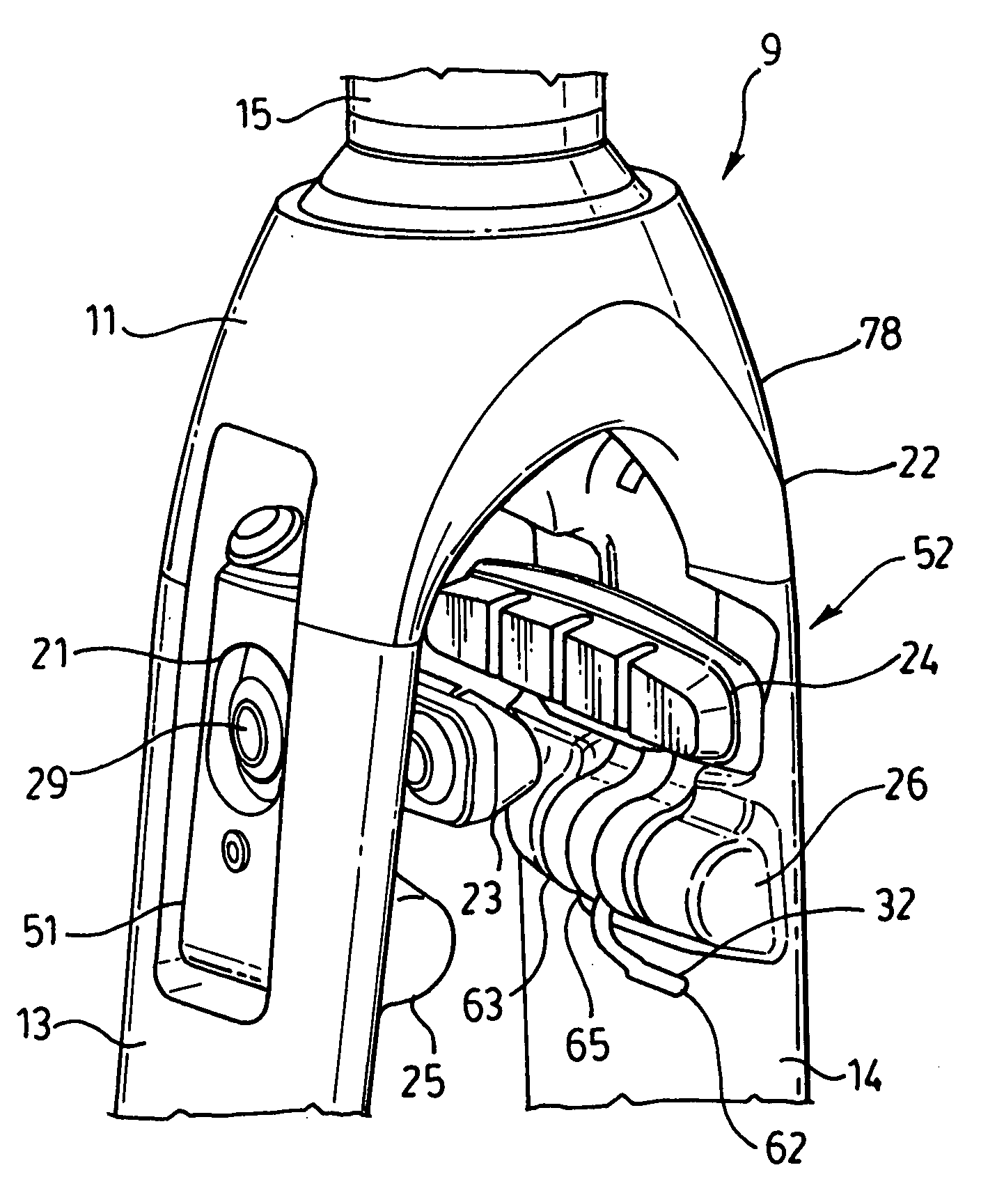
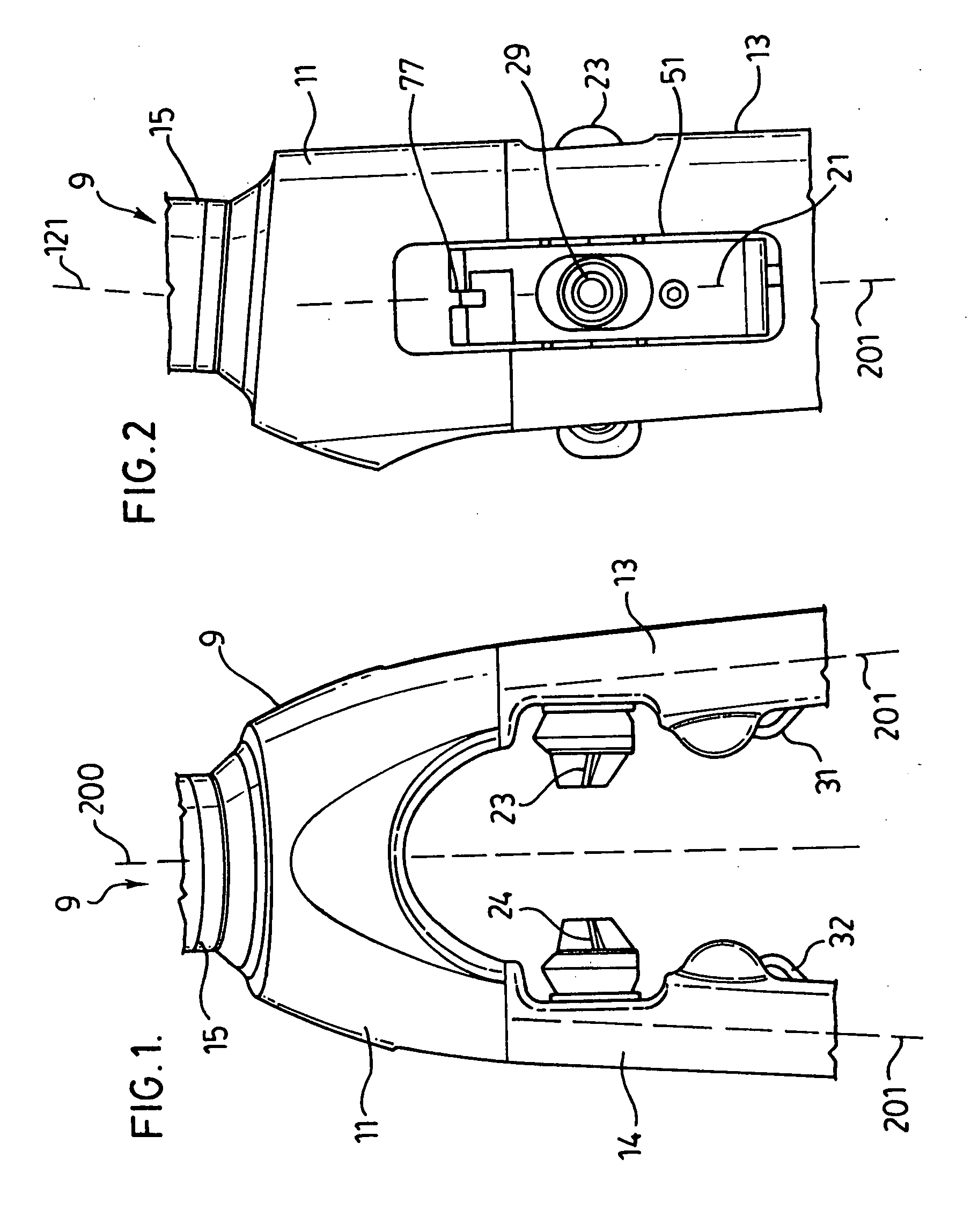
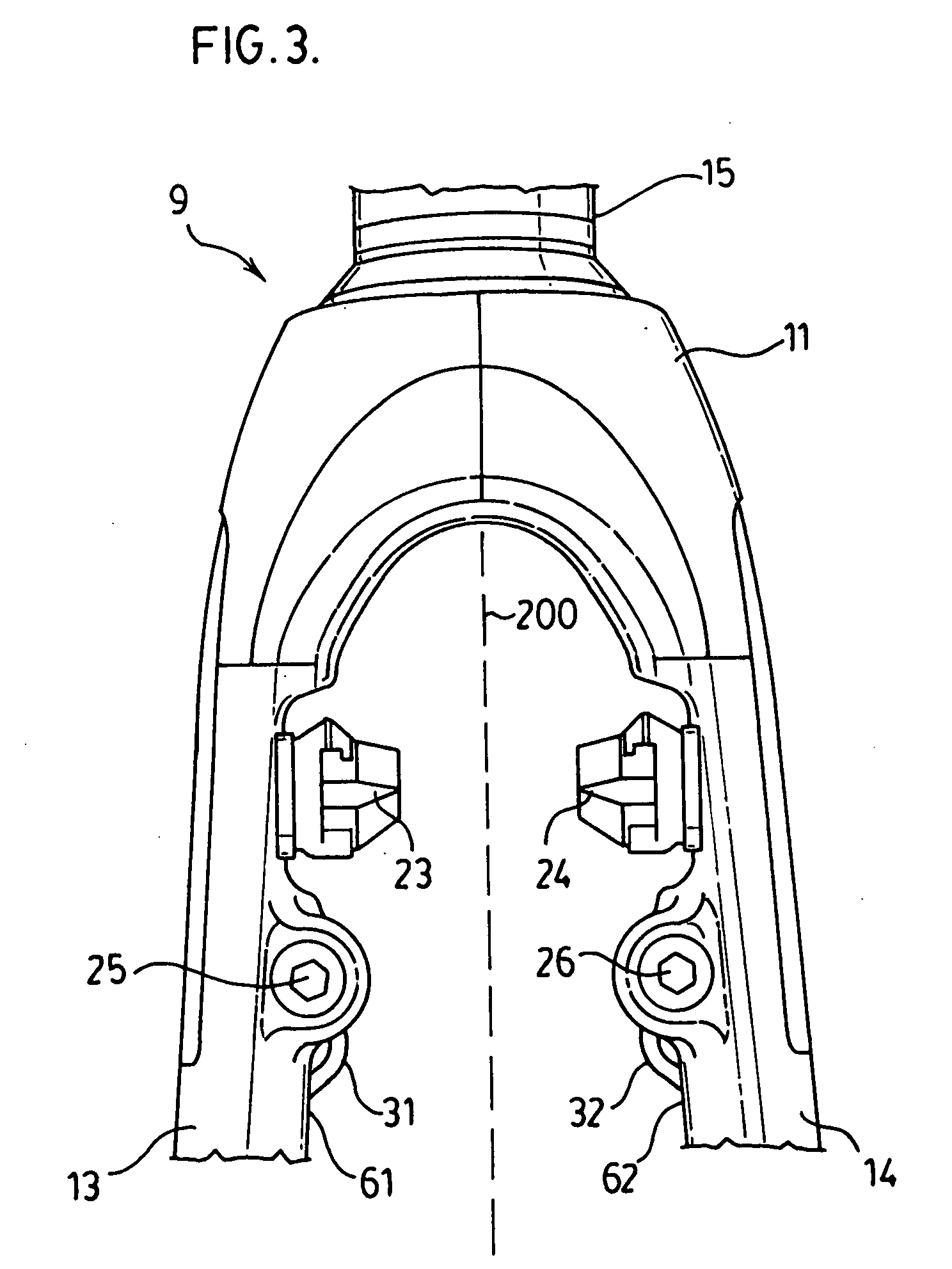
[0066] Reference is made to FIGS. 5 to 8, 17, 32 and 33 which illustrate an integrated fork with a rear mounted brake structure in which access openings or recesses 51, 52 are located at the rear of the fork 9 open to the rear and are cut out the fork legs 13, 14. This rear mounted brake structure allows the front of the fork 9 to be designed in an aerodynamic fashion and keeps the brake system hidden within the structure of the fork 9 as seen in front view in FIG. 5.

[0067] As shown in FIG. 6, the braking mechanism includes a straddle bridge 71 and straddle cable 75. The straddle cable 75 has ferrules 73, 74 at either end. The ferrules 73, 74 fit into slots 77, 78 at the end of the brake lever arms 21, 22. When the rider pulls on a brake hand operated lever (not shown) carried on the handle bars, a brake cable 99 pulls the straddle bridge 71 up into a cavity 97 at the rear of the crown 11. While not necessary the cable may extend from the straddle bridge 71 through a cable guide exi...


PUM


Abstract

A cycle with a wheel-supporting structure comprising a crown section and a pair of forklegs, a brake assembly with lever arms mounted at least partially within cavity openings within each fork leg to reduce aerodynamic drag.

Description

RELATED APPLICATION [0001] This application is related to and claims the benefit as under 35 U.S.C. 119 of U.S. Provisional Patent Application No. 60 / 836,685 filed Aug. 10, 2006FIELD OF THE INVENTION [0002] The present invention relates to cycles, more particularly bicycles and to an arrangement for integrating a brake mechanism into a wheel supporting structure including a crown section and a pair of fork arms. BACKGROUND OF THE INVENTION [0003] In the past, brakes typically have been attached to the fork legs of a bicycle either completely in front of or behind the forks themselves to provide for braking. The brakes could also be attached to the fork crown completely in front of or behind the fork. In one example, the brakes have a pivot bolt around which brake arm can rotate. The pivot bolt is secured to the outside of the fork legs. [0004] Such known braking systems have been appreciated by the present inventors as not reducing the aerodynamic drag on the bicycle at the least si...

Claims


Application Information

Patent Timeline
IPC IPC(8): B62L3/02B62K3/02
CPCB62L1/10B62K19/38B62K21/02
Inventor VROOMEN, GERARDWHITE, PHILIPCHAN, RODNEY MATTHEWSCHMIDER, JOHN
Owner WHITE PHILIP G & ANNA DOPICO AS TRUSTEES OF
Why Eureka
Try Eureka