Installing structure of wire harness

a technology of installing structure and wire harness, which is applied in the direction of machine supports, mechanical devices, and other domestic objects, can solve the problems of excessive length, high cost of support members, and excessive time and labor, and achieve the effects of preventing looseness, facilitating and positively absorbing, and enhancing the reliability of continuous supply of electric power to the movable structure body

Active Publication Date: 2008-02-14
YAZAKI CORP
View PDF15 Cites 27 Cited by
  • Summary
  • Abstract
  • Description
  • Claims
  • Application Information

AI Technical Summary

Benefits of technology

[0034]In the above configurations, the wire harness extending along the link is slidably passed through the single flexible protective tube, and therefore for example, as compared with the case where a plurality of separate protective tubes are used, the wire harness is prevented from becoming loose between such separate protective tubes, and also damage resulting from such looseness is prevented. A harness surplus length is easily and positively absorbed, and the reliability of continuous supply of electric power to the movable structural body is enhanced. And besides, the existing general-purpose part is used as the flexible protective tube, and therefore the cost of the parts is reduced.
[0035]In the above configurations, the wire harness is smoothly bent, together with each end portion of the protective tube, with a large radius, and therefore the folding of the wire harness and the concentration of stresses thereon are prevented, and the lifetime of the wire harness is prolonged, and the reliability of continuous supply of electric power is enhanced.
[0036]In the above configurations, the protective tube on the movable structural body, together with the wire harness portion, is smoothly bent with a large radius, and therefore the folding of the wire harness and the concentration of stresses thereon are prevented, and the lifetime of the wire harness is prolonged, and the reliability of continuous supply of electric power is enhanced.
[0037]In the above configurations, the radius of bending of the wire harness is larger than the radius of bending of the protective tube, and therefore the ability of the wire harness to slide within the protective tube is enhanced, and the catching, etc., of the wire harness are prevented, and the harness surplus length portion is smoothly moved (absorbed), and the reliability of continuous supply of electric power is enhanced.
[0038]In the above configurations, the drain holes are not closed by the wire harness, and therefore water drops, dirt, etc., within the protective tube are positively discharged via the drain holes, and the water drops, dirt, etc., are prevented from intruding into a connector, etc., to which the wire harness is connected, and the reliability of continuous supply of electric power is enhanced.
[0039]In the above configurations, the cost of the parts is reduced by the use of the corrugated tube which is an existing general-purpose part. And besides, the wire harness slides on the corrugated inner surface of the corrugated tube with a low friction, so that the ability to absorb the harness surplus length is enhanced.

Problems solved by technology

However, in the case where a wire harness is installed on a link, tension and a bending force act on the wire harness installed along the link in accordance with a pivotal movement of the link at the time of opening and closing the roof, and looseness (surplus length) develops in the wire harness.
However, if the wire harness is softly supported at a plurality of bent portions thereof, the cost of support members is high, and also much time and labor are required for the assembling operation, and furthermore there are fears that the wire harness may become loose between the support members and that damage and a shortened lifetime resulting from this looseness may be encountered.
Furthermore, when rainwater or the like intruding into the wire harness is left as it is, there are fears that incomplete contact of a connector and a malfunction of the auxiliary equipment resulting therefrom may be encountered.
These problems are not limited to the roof, but can be encountered also with other structures in which a door or other movable structural body is connected to a fixed structural body such as a vehicle body by links.

Method used


Image

  • Installing structure of wire harness
  • Installing structure of wire harness
  • Installing structure of wire harness

Examples


Embodiment Construction

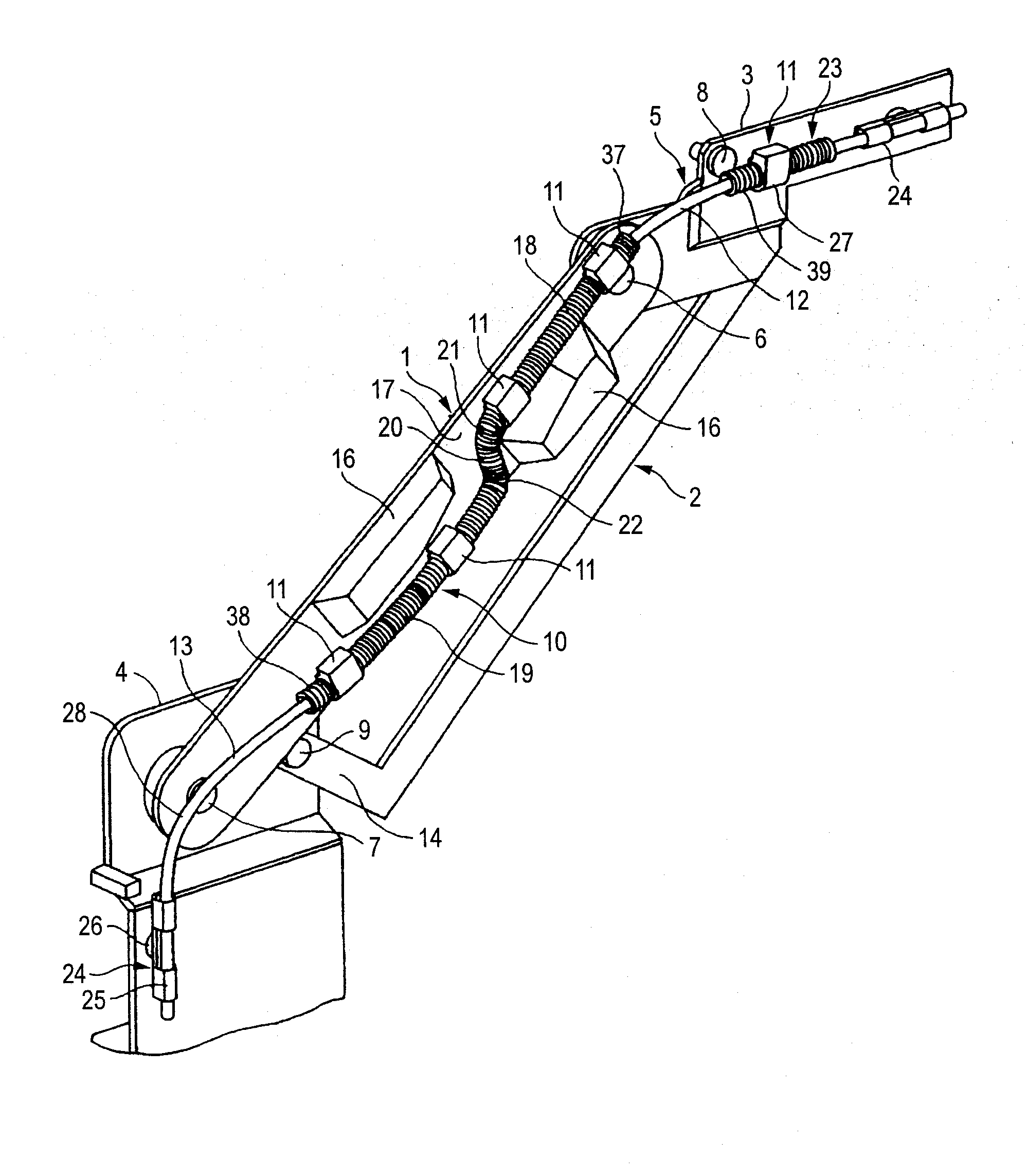
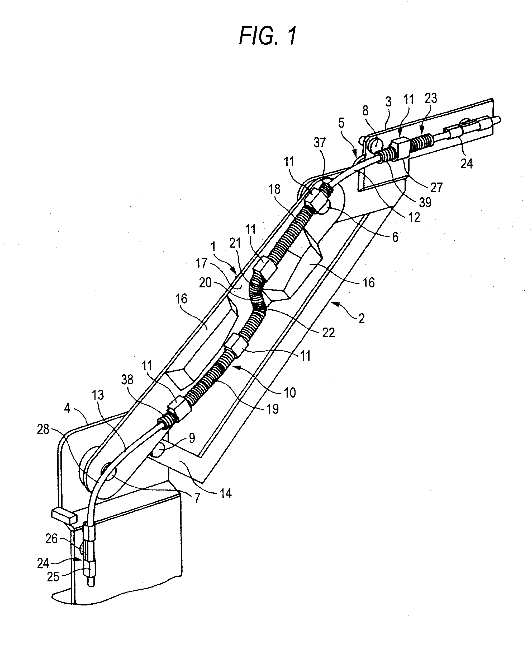
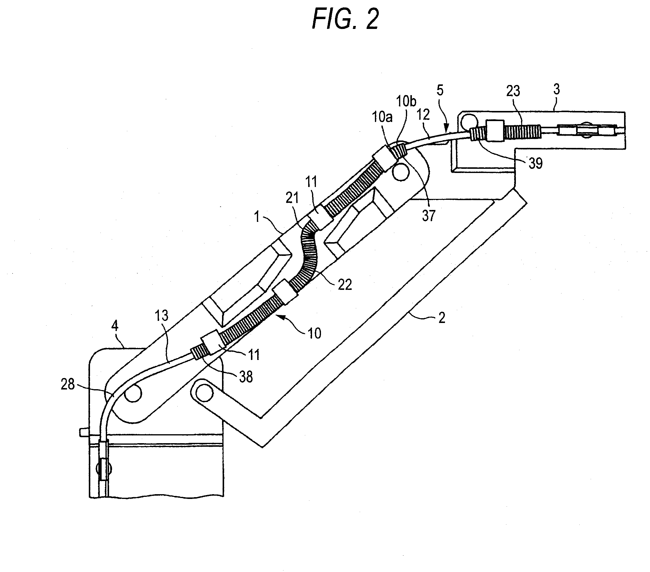
[0052]FIGS. 1 to 4 show one preferred embodiment of an installation structure (of installing a wire harness on a link) of the present invention. The link of this embodiment is so designed as to store a roof (not shown) of an automobile in a folded manner in a luggage space (not shown) at a rear portion of the vehicle.

[0053]FIGS. 1 and 2 show a closed condition of the roof in which two (upper and lower) links 1 and 2 are pivotally moved forwardly toward the front of the vehicle to be disposed upwardly obliquely, and FIGS. 3 and 4 show an open condition of the roof (the condition in which the roof is stored or stowed in the luggage space) in which the links 1 and 2 are pivotally moved rearwardly toward the rear of the vehicle to be disposed in a slightly downwardly-slanting position relative to a horizontal direction.

[0054]As shown in FIGS. 1 and 2, the wire harness (comprising a plurality of insulating sheathed wires) 5 is installed on the main link (pivotal link) 1 of a larger width...


PUM


Abstract

An installing structure of a wire harness on a link includes a link which pivotally connects a movable structural body to a fixed structural body, a wire harness which is installed along the link so as to extend from the fixed structural body to the movable structural body, a singular first flexible protective tube through which the wire harness is slidably passed, and a fixing member which fixes the flexible protective tube to the link.

Description

BACKGROUND OF THE INVENTION[0001]This invention relates to an installing structure of a wire harness on a link, in which the wire harness is installed along the link for opening and closing an automotive roof or the like.[0002]FIGS. 10 and 11 show one form of automotive roof storage structure employing a conventional link mechanism (see Patent Literature 1).[0003]This roof storage structure includes a pair of front and rear pivotal links 52 and 53 pivotally connected to a vehicle body 51, an intermediate upper fixing link 55 connected to the front pivotal link 52, a front upper fixing link 54 connected to the rear pivotal link 53, a soft-top roof 56 fixed to the front upper fixing link 54.[0004]In a completely-closed condition (not shown) of the roof 56, the front upper fixing link 54 and the intermediate upper fixing link 55 are arranged on a horizontal straight line, and the pair of front and rear pivotal links 52 and 53 are positioned generally upright. The pivotal links 52 and 5...

Claims


Application Information

Patent Timeline
Patent Type & Authority Applications(United States)
IPC IPC(8): F16L3/08
CPCF16L3/015
Inventor YAMAMOTO, MASATAKA
Owner YAZAKI CORP
Why Eureka
Try Eureka