Ultra-high sensitivity NDIR gas sensors

a gas sensor, ultra-high sensitivity technology, applied in the field of gas analysis, can solve the problems of non-specificity, long-term drift, and one of them without exception, and achieve the effect of reducing the number of white cells

a gas sensor, ultra-high sensitivity technology, applied in the field of gas analysis, can solve the problems of non-specificity, long-term drift, and one of them without exception, and achieve the effect of reducing the number of white cells

US20080035848A1Inactive Publication Date: 2008-02-14WONG JACOB Y

Image

  • Ultra-high sensitivity NDIR gas sensors
  • Ultra-high sensitivity NDIR gas sensors
  • Ultra-high sensitivity NDIR gas sensors

Examples


Embodiment Construction

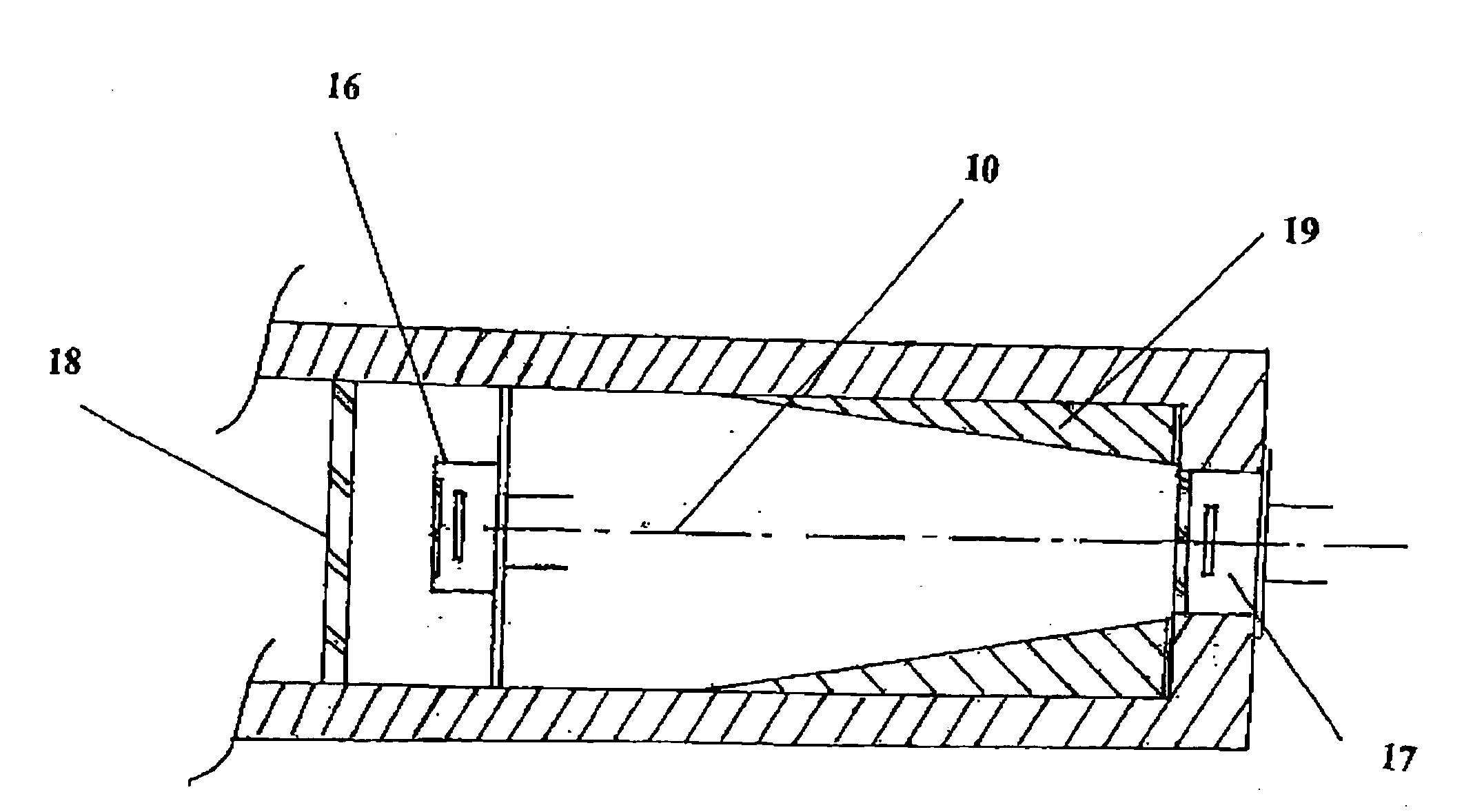
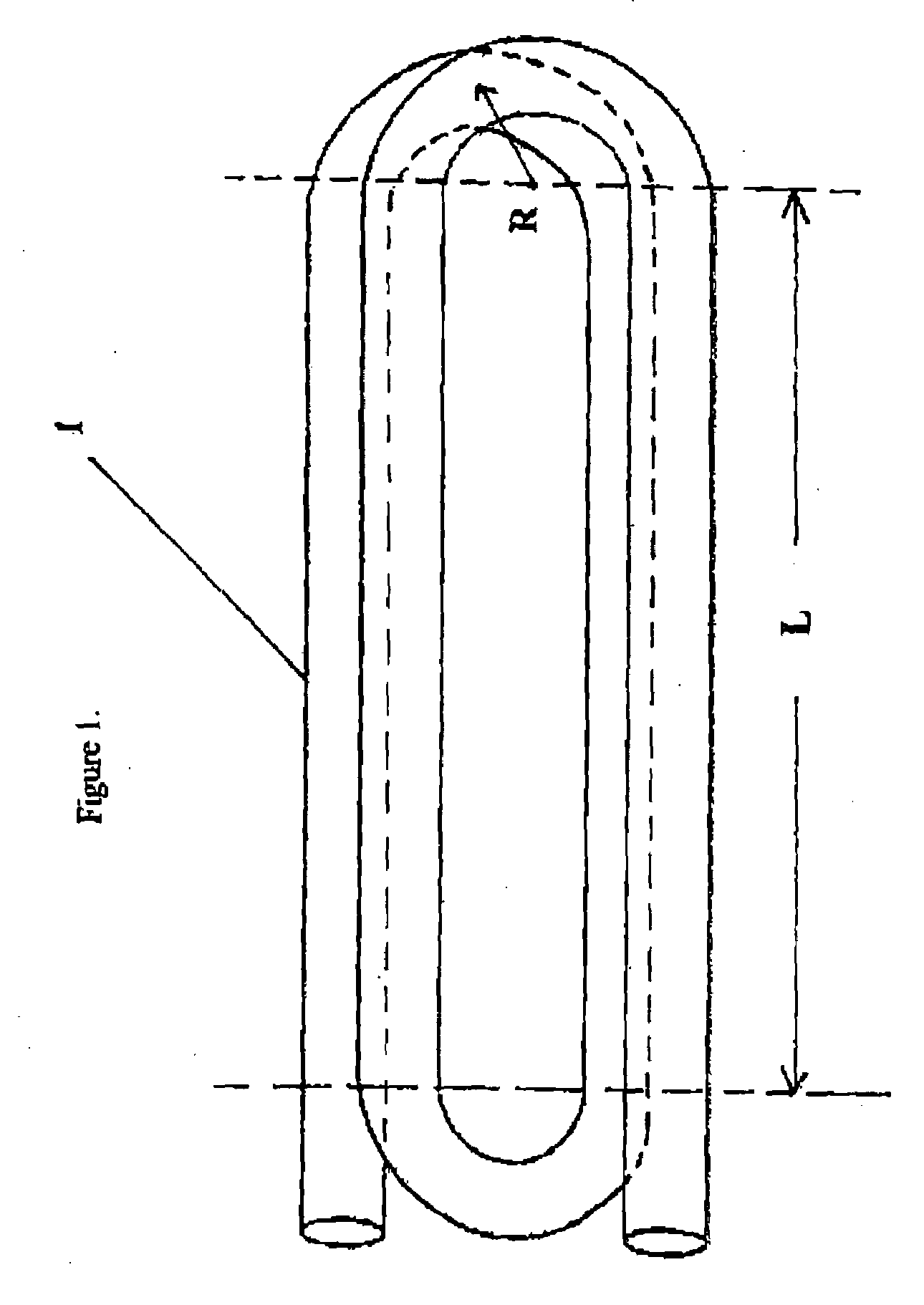
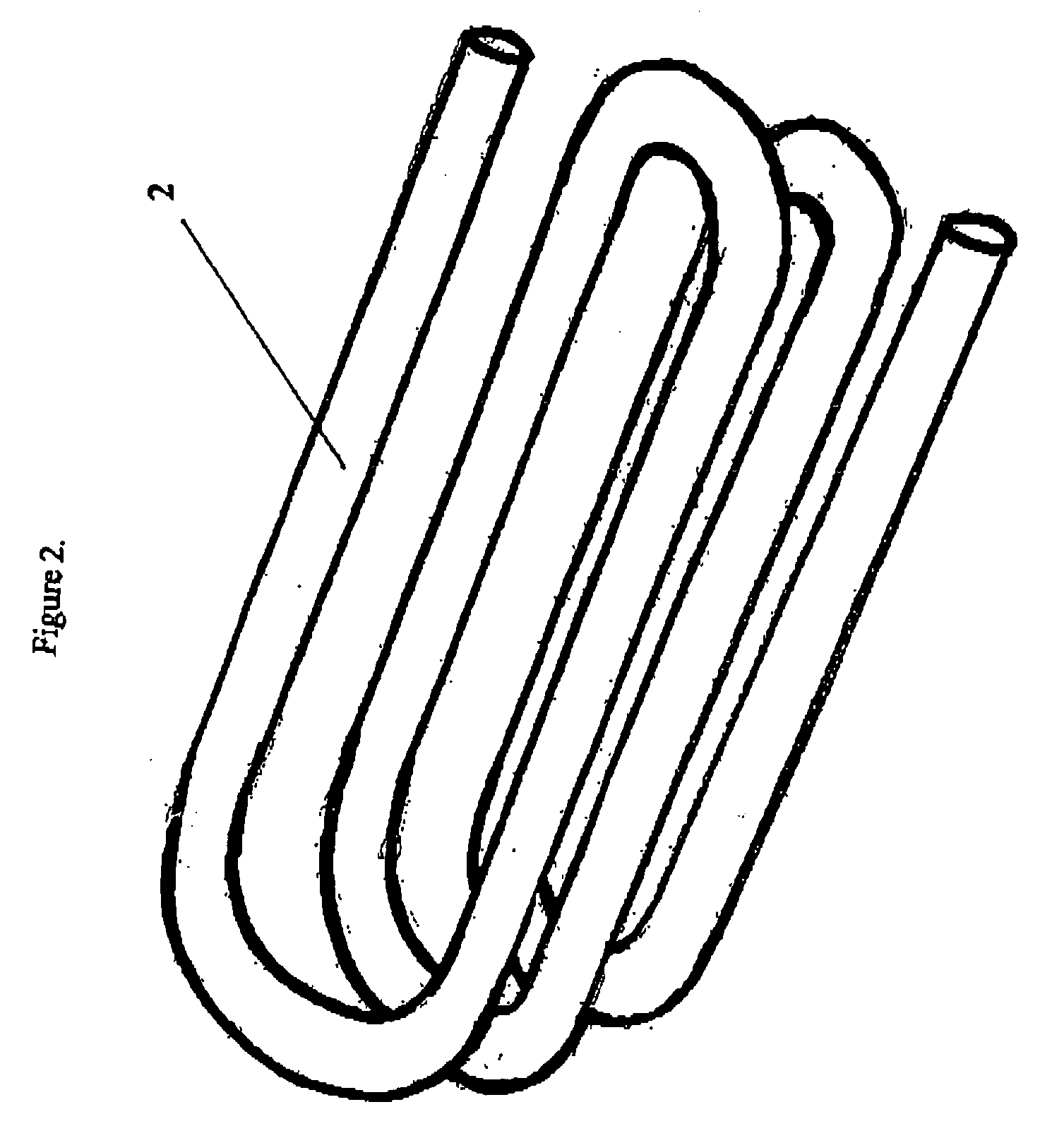
[0026]For over two decades, the present inventor diligently worked on simple, rugged and low-cost NDIR gas sample chambers culminating in the so-called ā€œwave-guideā€ sample chamber invention disclosed in U.S. Pat. No. 5,163,332 (1992). Indeed, for gases with moderate to strong absorption bands in the mid-infrared spectral region like CO2 (4.26 μm), H2O (2.7 μm), CH4 (3.4 μm) etc., the optimum and simplest gas sample chamber is a hollow straight metallic tube with arbitrary cross-section but speculatively reflective inner walls very much likened to a standard microwave wave-guide. Today after over a decade has gone by since the advent of the ā€œwave-guideā€ gas sample chamber (a.k.a., ā€œThe Tubeā€), most of the reliable, rugged, sensitive and low-cost CO2 sensors use this design, rendering a host of new applications, including faster and false-alarm resistant fire detectors and Demand Control Ventilation (DCV) strategies for saving energy in high-rise office and commercial buildings, many ...


PUM


Abstract

A compact and long path-length sample cell that is a hollow waveguide with a plurality of bends that are collectively greater than 180 degrees in three dimensions, a focusing device for quasi-focusing radiation into a beam with an angle of incidence between greater than approximately 0° and approximately 10° relative to a longitudinal axis of a first linear segment of the waveguide proximate a source of infrared radiation and a second focusing device for focusing infrared radiation after it has traveled through substantially all of the waveguide as it approaches a detector chamber. The sample cell can be used with two or more detectors to detect the concentrations of one or more gasses, to levels less than 100 ppm, after correction for water vapor.

Description

CROSS-REFERENCE TO RELATED APPLICATIONS[0001]This application is related to an application filed concurrently herewith, with the same inventor, entitled ā€œMethod for Detecting a Gas Species Using a Super Tube Waveguide,ā€ attorney docket number RLA35.124.FIELD OF THE INVENTION[0002]The present invention is in the field of gas analysis and more particularly relates to a compact and long path-length sample cell for use in measuring very small concentrations of a gas based upon the absorption of infrared radiation as it passes through the gas within the sample chamber.BACKGROUND OF THE INVENTION[0003]Certain gases have absorption bands in the electromagnetic spectrum that absorb so weakly that absorption can only be detected after the radiation has traveled a relatively long distance, perhaps as long as tens of meters, through the gas. In other situations the gases of interest might have adequate absorption strengths but they must be detected in very low concentrations, typically in the ...

Claims


Application Information

Patent Timeline
14 Feb 2008
Publication
US20080035848A1
IPC
G01J5/02; G01N21/01
CPC
G01J3/02; G01J3/021; G01J3/024; G01J3/0256; G01J3/108; G01J3/36; G01N2021/3545; G01N21/0303
Inventors
WONG, JACOB Y.