Antenna coil

a technology of antenna coil and coil body, which is applied in the direction of loop antennas with ferromagnetic cores, polarised antenna unit combinations, cores/yokes, etc., can solve the problem of counter to the notion of minimizing device size, and achieve the effect of reducing weight, favorable reception sensitivity, and small siz

Inactive Publication Date: 2008-02-14
DENSO CORP
View PDF14 Cites 24 Cited by
  • Summary
  • Abstract
  • Description
  • Claims
  • Application Information

AI Technical Summary

Benefits of technology

[0006] The present invention was created to resolve the sorts of problems discussed above that conventional antenna coils present, its aim being to supply an antenna coil whereby smaller sizes and reduced weight can be devised. Another aim is to supply an antenna coil whereby favorable reception sensitivity can be obtained with minimal interference.

Problems solved by technology

However, when multiple antenna coils are arranged in this way along the X-axis and Y-axis of the receptor's circuit substrate, the surface area occupied by the antenna coil component in the aforementioned circuit substrate rises and thus the device itself that is equipped with the antenna coil must be made large, which is counter to the notion of minimizing device size.
Furthermore, there are cases where individual bar antennas interfere with each other and the anticipated reception sensitivity does not materialize.

Method used


Image

  • Antenna coil
  • Antenna coil
  • Antenna coil

Examples


second embodiment

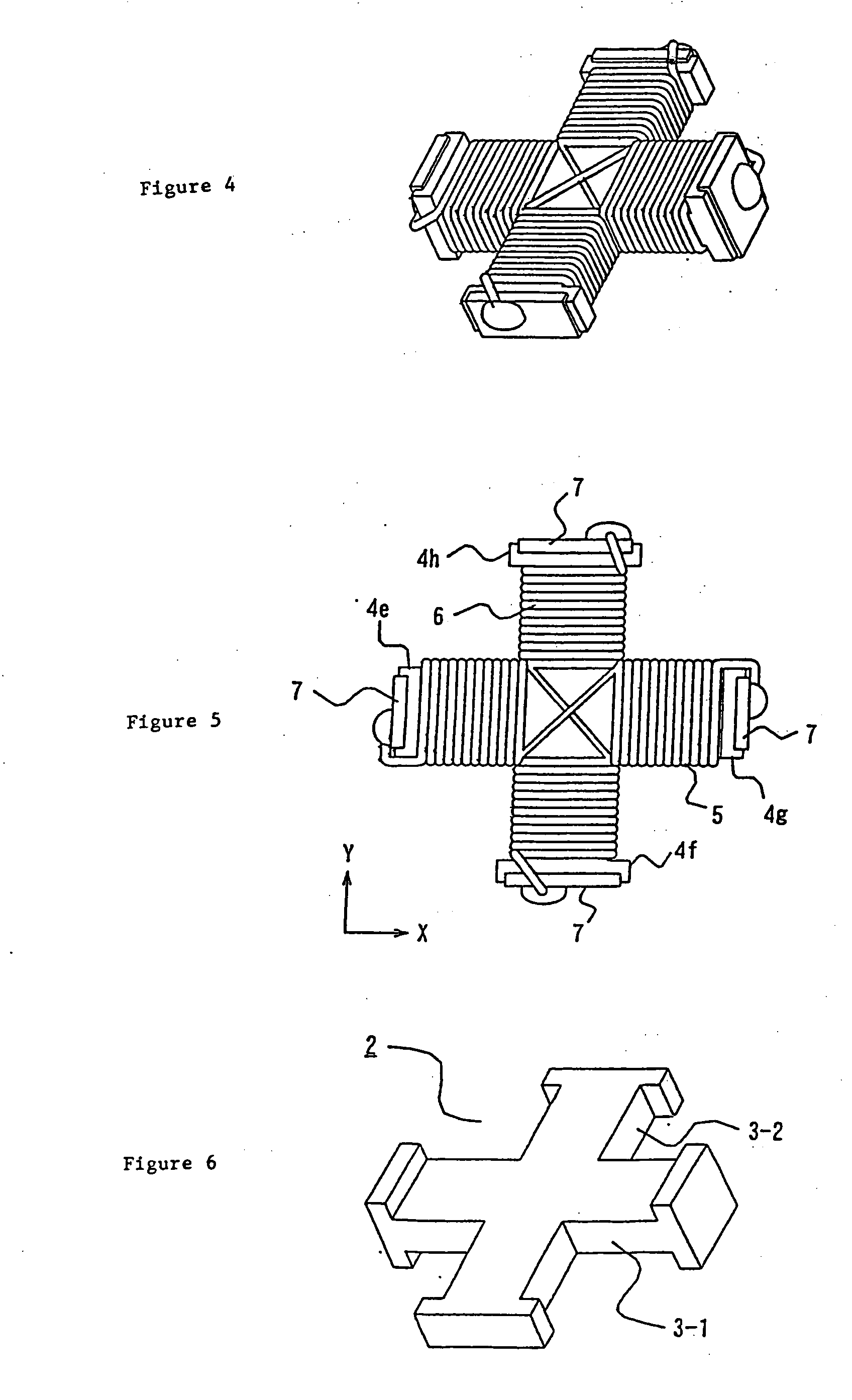
[0033] As for the second embodiment depicted in FIG. 4 and FIG. 5, the configuration of the ferrite core (2) in the example shown is cruciform. The first coil (5) is wound at site 3-1, an X-axis extension of coil component (3). Its starting end and ending end are connected to the electrodes formed in the protrusions (4e), (4g), respectively. Moreover, the second coil (6) is wound at site 3-2 on a Y-axis extension of the winding coil component (3). Its winding start end and winding finish end are connected, respectively, to electrodes (7) formed in protrusions (4f), (4h).

[0034]FIG. 7 and FIG. 8 show a third embodiment that differs from the two aforementioned embodiments. (8) is a winding rod made of insulating resin, etc. in whose center area is formed a hole and indentation (9). Rim parts (11a), (11b) are formed that protrude parallel to the periphery at the top and bottom of the wall component (10). (12) is a third coil wound on the outer circumference of the wall component (10) of...

third embodiment

[0036] Furthermore, in the third embodiment depicted by FIG. 7 and FIG. 8, the number of loops in the respective coils is adjusted just as described above so that the electric field intensity and the magnetic field intensity evoked, respectively, by the first coil (5) and second coil (6) that form the first antenna coil component (13), and by the third coil (12) that forms the second antenna coil, are approximately equal. Moreover, when the first coil (5), the second coil (6), and the third coil (12) form respectively independent tuning circuits, the various tuning circuits are connected to a high frequency modulation circuit, and said high frequency modulation circuit selectively modulates the more intense output signal of the various tuning circuits. Said high frequency modulation circuit selectively modulates the output signal of the tuning circuit forming the first coil (5) relative to the electromagnetic waves incident from the X-axis, the output signal of the tuning circuit fo...

fourth embodiment

[0037]FIG. 9 through FIG. 11 depict an antenna coil related to a In this antenna coil is a structure whereby wound onto a base component (20) comprising a flat bar are a first coil (5), a second coil (6), and a third coil (12). The first coil (5) is wound so that the X-axis of the base is the axis. The second coil (6) is wound so that the Y-axis of the base is the axis. The third coil (12) is wound so that the Z-axis of the base is the axis. The base component (20) consists of ferrite.

[0038] Base (20) has an approximately right-angled parallelepiped configuration. Tabs (21) are provided on the eight corners of this parallelepiped base (20). The flat configuration of the aforementioned tabs (21) are quarter-circled fan shapes. In the surface of base (20) is formed a second groove (22) deepest in the X-axis direction when the base (20) is placed in a flat state. Wound onto this second groove (22) is the second coil (6). The second lateral components (21b) of the tabs (21) are arrange...


PUM

PropertyMeasurementUnit
diameteraaaaaaaaaa
thicknessaaaaaaaaaa
thicknessaaaaaaaaaa

Abstract

The size of an antenna coil is reduced, and it is possible to prevent a lowering of the reception sensitivity due to a difference of the arrangement position of the antenna coil. On a winding frame of a ferrite core, a first coil and a second coil are wound in such a manner that their winding axes orthogonally intersect each other. A third coil is wound around an outer circumference of the first coil and the second coil in such a manner that the third coil's winding axis orthogonally intersects the winding axes of the first coil and the second coil.

Description

[0001] This application is a division of application Ser. No. 10 / 506,565, filed under 35 U.S.C. § 371 on Sep. 3, 2004, which claims the benefit of priority to Japanese Patent Application No. 2002-58835, filed on Mar. 5, 2002, the entire disclosures of which are incorporated herein by reference.TECHNICAL FIELD [0002] The present invention relates to a small-sized antenna coil used in, for example, the receptor of a keyless entry system and anti-theft device to open and close locked and unlocked cars by remote control. PRIOR ART [0003] Conventionally, bar antenna coils wound lengthwise along a bar-shaped ferrite core are frequently used as antenna coils in the receptors of this sort of keyless entry system and antitheft device. [0004] In other words, a bar antenna coil structured as discussed above has directionality whereby reception sensitivity is highest to wavelengths incident from the direction parallel to the lengthwise axis of the ferrite core and lowest to wavelengths incident...

Claims


Application Information

Patent Timeline
Patent Type & Authority Applications(United States)
IPC IPC(8): H01Q7/06H01F3/00H01Q7/08H01Q21/24
CPCH01F3/00H01Q21/24H01Q7/08H01F2003/005
Inventor UEDA, HOZUMINISHINO, TATSUMIKITAHARA, TAKAHIDE
Owner DENSO CORP
Why Eureka
Try Eureka