Display System and Camera System

a display system and camera technology, applied in the field of display systems and camera systems, can solve the problems of requiring considerable labor and time for a large number of two-dimensional images, and achieve the effects of high accuracy, high accuracy, and reasonable labor and tim

Active Publication Date: 2008-02-14
HITACHI LTD
View PDF6 Cites 88 Cited by
  • Summary
  • Abstract
  • Description
  • Claims
  • Application Information

AI Technical Summary

Benefits of technology

[0005] By the way, since technologies described in JP-A-2001-103515 and JP-A-2002-27504 enable making use of an after-image to provide for stereophonic vision, it is required that slightly different images be displayed substantially at the same time. Therefore, fairly many two-dimensional images are needed to take considerable labor and time, and a high volume memory is needed to hold data

Problems solved by technology

Therefore, fairly many two-dimensional images are needed to take considerable labor an

Method used


Image

  • Display System and Camera System
  • Display System and Camera System
  • Display System and Camera System

Examples


first embodiment

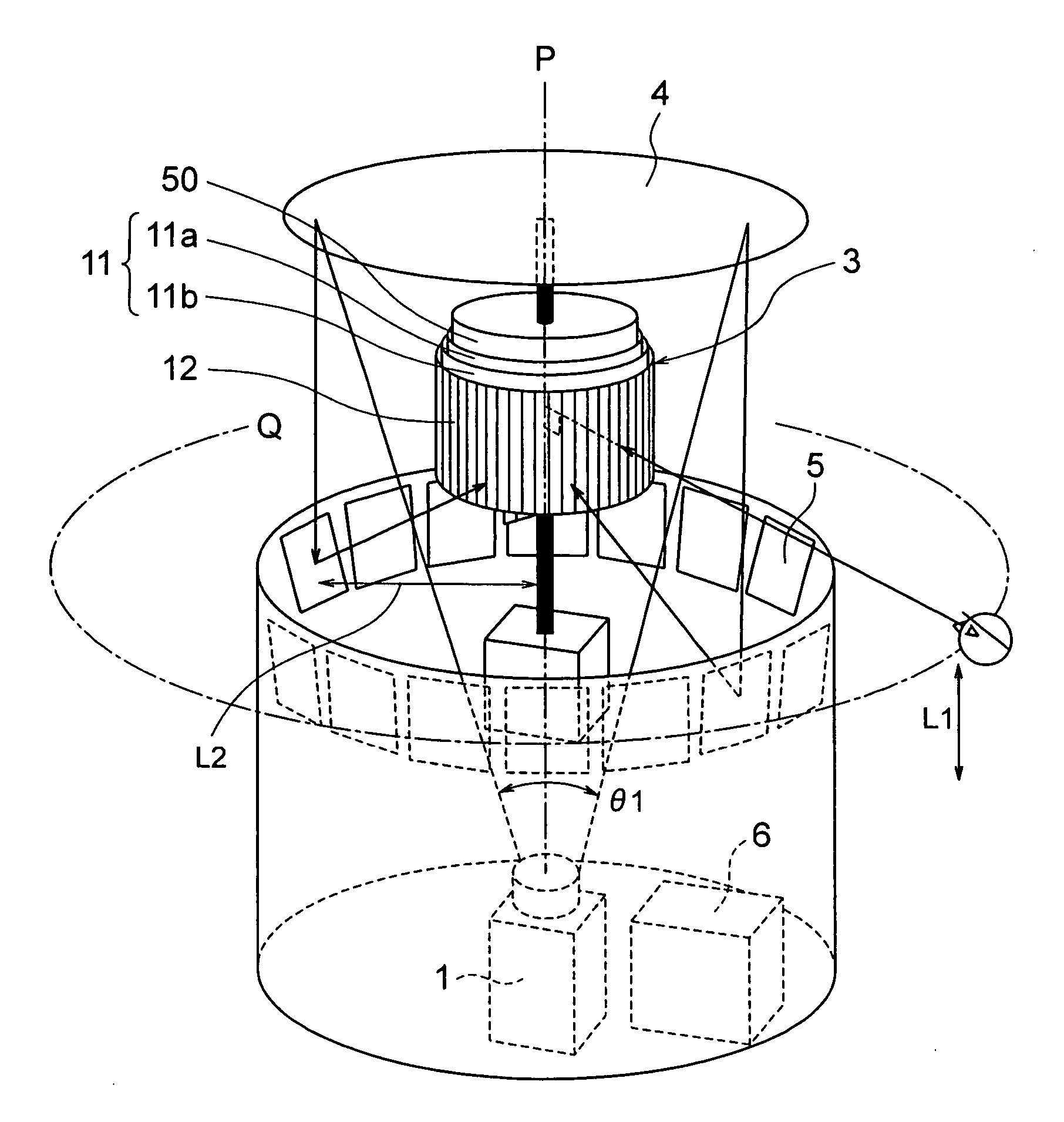
[0053] FIGS. 1 to 13 show a first embodiment. First, an outline construction of a display system according to the first embodiment will be described with reference to FIG. 1. FIGS. 1 to 11 are views illustrating the display system and FIGS. 12 and 13 are views illustrating a camera system.

[0054]FIG. 1 is a perspective view showing an outward appearance of the display system according to the first embodiment. In FIG. 1, the display system according to the embodiment comprises an electronic projector 1 that projects various images, a stereoscopic screen 3 that finally receives an image from the electronic projector 1 to display the image, a plurality of polygonal mirrors (mirror groups) 5 arranged around the stereoscopic screen 3, an auxiliary mirror 4 that guides a projected light from the electronic projector 1 to the polygonal mirrors, and a control unit 6 that generally controls the display system.

[0055] The stereoscopic screen 3 comprises, on an outer peripheral surface thereof...

second embodiment

[0106]FIG. 14 is a view showing a construction of a display system according to a second embodiment. In FIG. 14, according to the second embodiment, the display system is connected to a camera system 17 through a communication path 18. With the camera system 17, when a projected image is obtained by a CCD camera 13 in the way illustrated in FIG. 12, the projected image is processed to create an image signal such as NTSC / PAL to transmit the same to the display system via the communication path 18. In the display system, when the image signal is received, it is converted into an original projected image and fed to an electronic projector 1. Thereby, image segments of the body 15 obtained in the camera system are displayed on a stereoscopic screen 3 in the same manner as in the preceding first embodiment and besides, a stereoscopic image can be displayed in real time together with creation of the projected image.

[0107] Here, the communication path 18 may be a wire path or wireless. Al...

third embodiment

[0109]FIG. 15 is a view showing a construction of a display system according to a third embodiment. In FIG. 15, according to the third embodiment, the display system is mounted in the street and detects people who approach from four quarters to visually inform the approaching people of various guides.

[0110] According to the embodiment, approach of a person can be detected by using a method, in which sensors 19 are provided in a plurality of locations around the display system as shown in FIG. 15, or a mat switch is laid on a floor surface while not shown. Also, as measures of detecting directions a to p (FIG. 4) related to viewers, it suffices to use infrared rays, proximity switches, and microphones, of which number (for example, 16 in the a to p directions) corresponds to that of directions being desired to detect. At this time, it is possible to detect general movements of viewers on the basis of changes in signals, which are obtained from adjacent sensors.

[0111] Presently, ass...


PUM


Abstract

A display apparatus and an imaging apparatus constructed such that a high-resolution clear three-dimensional video image can be viewed from any direction. The display apparatus projects frame images, projected from a projector such as an electronic projector, to a video image projection surface of a three-dimensional screen through a polygonal mirror provided around the three-dimensional screen, thereby providing a polyhedral video image such as a three-dimensional image to a person viewing from around the video image projection surface. The three-dimensional screen has a view field angle limiting filter and a directional reflection screen. The view field angle filter limits the angle of a view field in the left/right direction, the angle being the angle of the projection on the video image projection surface (50) of the screen. The directional reflection screen has two sheets in horizontal and vertical directions. Furthermore, a projection light path between the electronic projector and the polygonal mirror is formed by refracting light through an auxiliary mirror.

Description

TECHNICAL FIELD [0001] The present invention relates to a display system, in which an image conformed to a direction seen from around a stereoscopic screen is displayed, and a camera system. BACKGROUND ART [0002] Conventionally, a display system has been proposed, in which a rotating screen is used to display a stereoscopic image. As an example thereof, two-dimensional image data of a body when the body is seen in respective surrounding directions are created from three-dimensional image data representative of a three-dimensional body (In addition, when two-dimensional image data are created from such three-dimensional image data, a hidden surface removal processing for removal of data of an unseen part is performed) and projected successively onto a rotating screen, and as the screen is varied in orientation upon rotation, two-dimensional images projected thereonto are changed successively. According to this, in the case where the screen is seen from a certain point, an image displ...

Claims


Application Information

Patent Timeline
IPC IPC(8): G02B27/22G03B21/28H04N13/363H04N13/388
CPCG02B27/2271G03B37/00G09F19/14G09F19/16G09F19/18H04N13/0488H04N13/0285H04N13/0447H04N13/0459H04N13/0468H04N13/0242H04N13/243H04N13/388H04N13/363H04N13/366H04N13/286H04N13/351G02B30/50
Inventor OTSUKA, RIEKOHOSHINO, TAKESHIHORII, YOUICHI
Owner HITACHI LTD
Why Eureka
Try Eureka