Hologram Record Carrier, Hologram Apparatus and Recording Method

a technology of hologram record carrier and hologram recording layer, which is applied in the field of record carrier, can solve the problems of deteriorating recording characteristic, wasteful use of holographic recording layer performance, and rotator of bisect azimuth, and achieve the effect of stable carrying and recording and reproduction stability

Inactive Publication Date: 2008-02-14
PIONEER CORP
View PDF3 Cites 8 Cited by
  • Summary
  • Abstract
  • Description
  • Claims
  • Application Information

AI Technical Summary

Benefits of technology

[0009] It is therefore an exemplary object of the present invention to provide a holographic record carrier, a recording / reproducing and hologram device capable of providing recording and reproduction stability.
[0010] Thus, as for a problem to be solved by the present invention, it is given as an example to provide a holographic record carrier which is capable of stably carrying out recording or reproduction, a method of recording or reproducing a hologram and a hologram apparatus.

Problems solved by technology

However, the conventional method involves a problem that the bisect azimuth rotator and the objective lens must be integrally driven.
The conventional method also has a problem of a deteriorated recording characteristic from reproduced light corresponding to the vicinity of the division boundary of the bisect azimuth rotator.
In the case that a hologram is recorded in such a holographic record carrier of reflective type, four kinds of hologram are recorded by interference due to four light beams of entering reference light and signal light and reflected reference light and signal light, thereby wastefully using holographic recording layer performance.
Further, when reproducing information, it is difficult to separate diffracted light caused by a reproduced hologram from reflected reference light, because the reference light is reflected from the reflective film of the holographic record carrier.
Accordingly, readout performance of the reproduced signal is deteriorated.
Further, since a reflected hologram image is recorded, the reproduced signal is deteriorated.

Method used


Image

  • Hologram Record Carrier, Hologram Apparatus and Recording Method
  • Hologram Record Carrier, Hologram Apparatus and Recording Method
  • Hologram Record Carrier, Hologram Apparatus and Recording Method

Examples


example 1

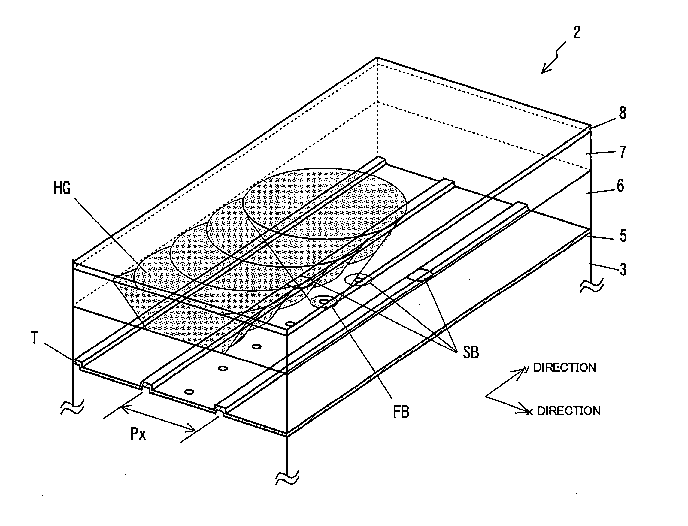
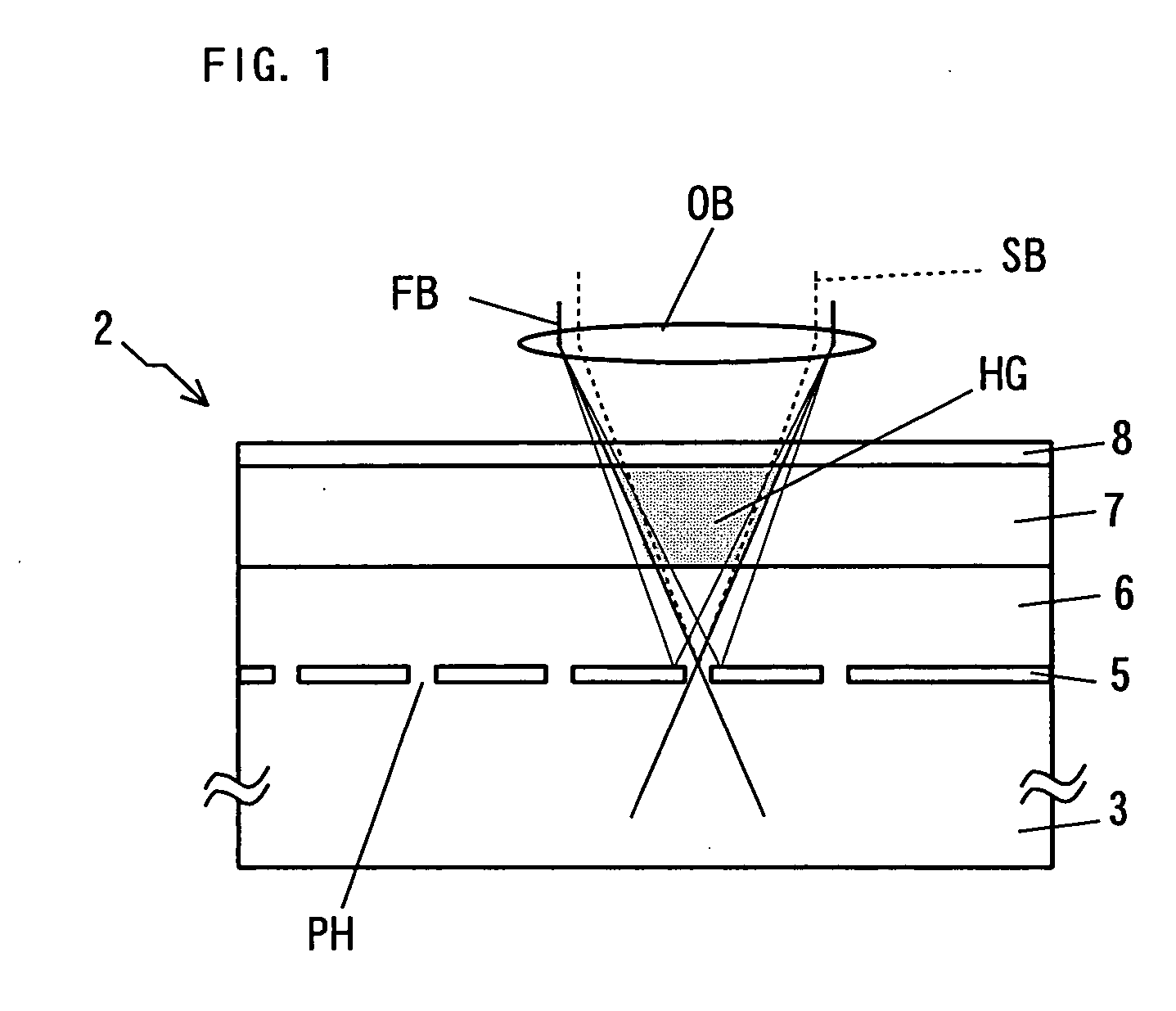
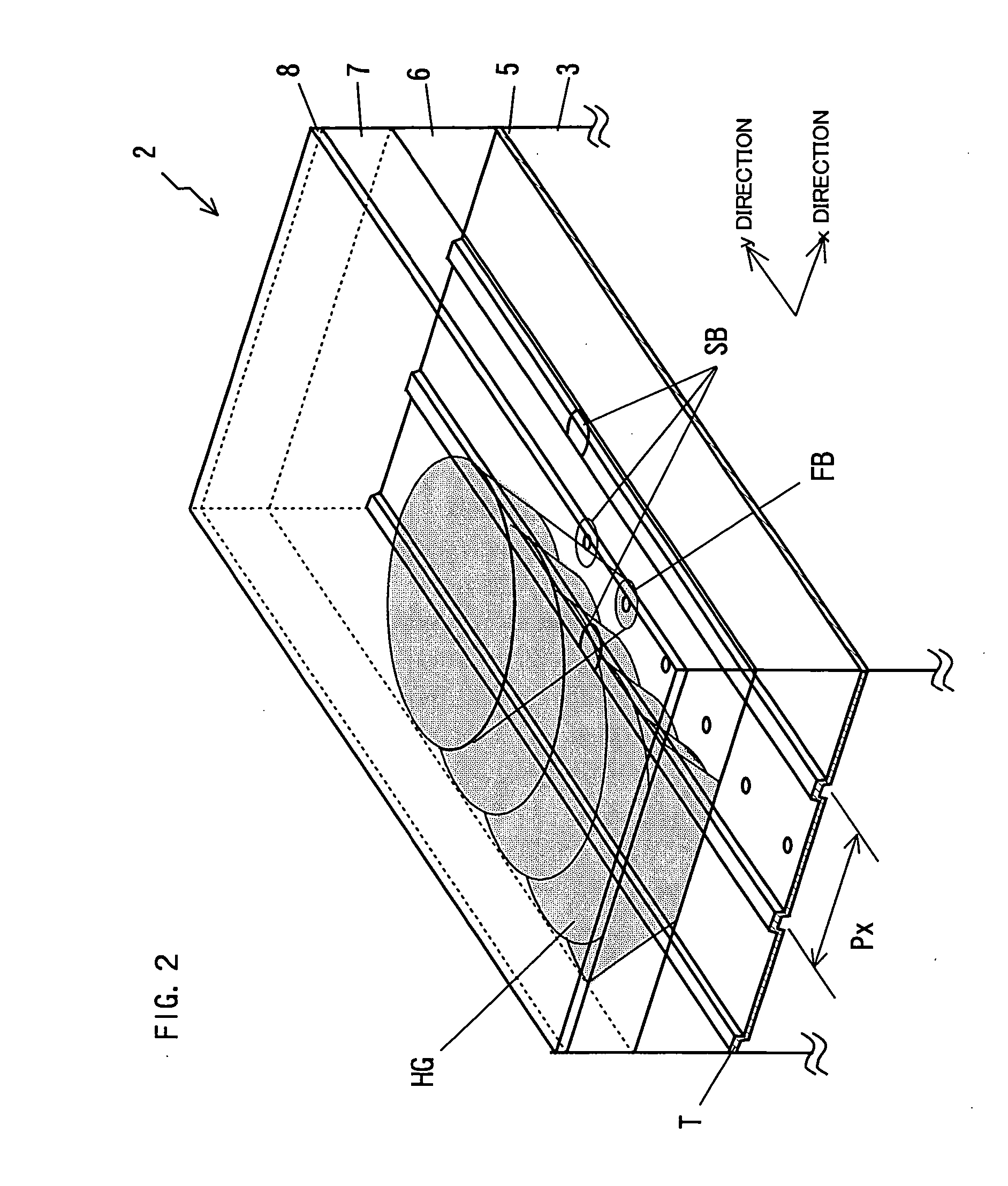
[0103] As shown in FIG. 15, the reflective function layer 5 of Example 1 has the tracks for which hologram multiplex intervals Px in the x-direction are set and which extends in the y-direction as a hologram multiplex direction in the form of a disc format. Note that, the servo control for the positioning with the holographic record carrier 2 is constantly performed by using the servo beam SB, and at the same time, the hologram recording is performed by using the first light beam FB.

[0104] As shown in the figure, at the time of recording, the spot of the servo beam SB which is condensed on the reflective function layer 5 of the holographic record carrier 2 is arranged forward of the spot of the first light beam FB in the y-direction as the recording direction of the holographic record carrier 2. The intervals in this arrangement between the first light beam FB and the servo beam SB are set to a hologram multiplex interval Py in the y-direction. The servo beam SB is divided into thr...

example 2

[0105] As shown in FIG. 16, Example 2 has the tracks T for which the hologram multiplex intervals Px in the x-direction are set and which extend in the y-direction as the hologram multiplex direction, and a mark Y agreeing with the multiplex intervals Py in the y-direction as a disc format.

[0106] As shown in the figure, at the time of recording, the spot of the servo beam SB is disposed forward of the spot of the first light beam FB in the y-direction as the recording direction of the holographic record carrier 2. The intervals in this arrangement of these spots are set to the hologram multiplex interval Py in the y-direction in the same manner as that in Example 1. For the servo beam SB, in addition to the tracking servo control similar to that in Example 1, time-base servo control for causing the objective lens OB to follow in the y-direction as well by utilizing the mark Y in the y-direction is simultaneously performed. The boring of the pinhole PH by the servo beam SB is simila...

example 3

[0107] As shown in FIG. 17, the disc format is similar to that in Example 2.

[0108] As shown in the figure, the spot of the servo beam SB is arranged forward of the spot of the first light beam FB in the y-direction as the recording direction of the holographic record carrier 2. The intervals in this arrangement of these spots are set to the hologram multiplex interval Py in the y-direction in the same manner as that in Example 1. For the servo beam SB, in addition to the tracking servo control similar to that in Examples 1 and 2, the time-base servo control for causing the objective lens OB to follow in the y-direction as well by utilizing the mark Y in the y-direction is simultaneously performed. In Example 3, the servo beam SB is set at an optical output where light-transmissive grooves can be bored in the reflective function layer 5 formed on the tracks, and the light-transmissive grooves are continuously bored. After that, the holographic record carrier 2 is moved in the y-dire...


PUM

PropertyMeasurementUnit
transmittanceaaaaaaaaaa
reflectivityaaaaaaaaaa
wavelengthaaaaaaaaaa

Abstract

A holographic record carrier is a holographic record carrier in or from which information is recorded or reproduced by irradiation of light, comprising: a holographic recording layer for storing a light interference pattern based on components of coherent reference light and signal light as a diffraction grating in the inside thereof; and a reflective function layer laminated on a side opposite to the light incidence side of the holographic recording layer, the reflective function layer being sensitive to the intensity of irradiated light so that a non-reflective region appears in an irradiated portion thereof.

Description

TECHNICAL FIELD [0001] The present invention relates to a record carrier such as an optical disk or card or the like with which information is optically recorded or reproduced, and more particularly, to a holographic record carrier which has a recording layer irradiated with an optical beam for recording information thereon or reproducing information therefrom, and a hologram apparatus and a hologram recording method therefor. BACKGROUND ART [0002] A hologram has drawn attention because of its ability to record two-dimensional data at a high density, for use in high density information recording. The hologram is characterized by volumetrically recording a wave front of light, which carries out recording of information on a recording medium made of a photosensitive material such as a photo-refractive material as changes in refractive index as a refraction grating. Multiplex recording on the holographic record carrier can dramatically increase the recording capacity. There are include...

Claims


Application Information

Patent Timeline
Patent Type & Authority Applications(United States)
IPC IPC(8): G03H1/18G03H1/02G03H1/26G11B7/0065G11B7/007G11B7/135G11B7/24044G11B7/24062
CPCG11B7/0065G11B7/24062G11B7/24044G11B7/00736
Inventor OGASAWARA, MASAKAZU
Owner PIONEER CORP
Why Eureka
Try Eureka