
Surge suppression system for power over network cables

Inactive Publication Date: 2008-02-14
A C DATA SYST INC
View PDF26 Cites 28 Cited by
  • Summary
  • Abstract
  • Description
  • Claims
  • Application Information

AI Technical Summary

Benefits of technology

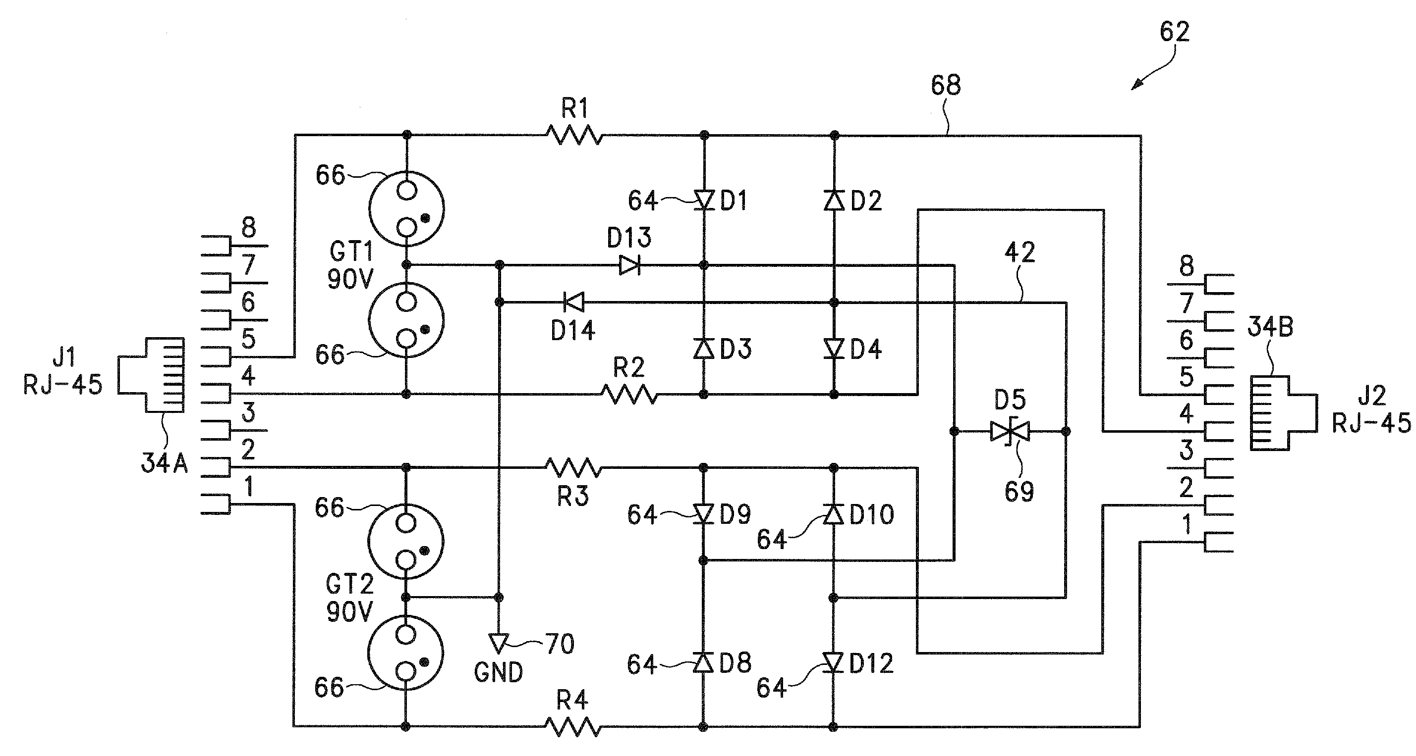
[0009] A Power over Ethernet (PoE) surge suppression system uses Schottky diodes to improve voltage clamping. In addition, Metal Oxide Varistors (MOVs) are used on separate PoE power conductors to provide increased power transmission. In one embodiment, a surge suppression unit includes multiple surge suppression modules configured for inserting into different slots in a same enclosure. The surge suppression modules can be quickly and easily inserted and then removed for connection with different communication cables.

Problems solved by technology

Conventional surge suppressors are generally not expandable to accommodate additional suppression needs.
Consumers are unable to simply upgrade their current surge suppressors to increase capacity.
Conventional surge suppressors are also bulky and inefficient in their use of box space.
Also, existing surge suppression assemblies are not capable of swapping out damaged or destroyed surge suppression modules without disrupting the operation of other surge suppression modules that may currently be operating in the same enclosure.
However, existing PoE surge suppression systems have power clamping limitations.
Existing PoE surge suppression systems can limit the amount of rated power that can be supplied to network devices.

Method used


Image

  • Surge suppression system for power over network cables
  • Surge suppression system for power over network cables
  • Surge suppression system for power over network cables

Examples


Embodiment Construction

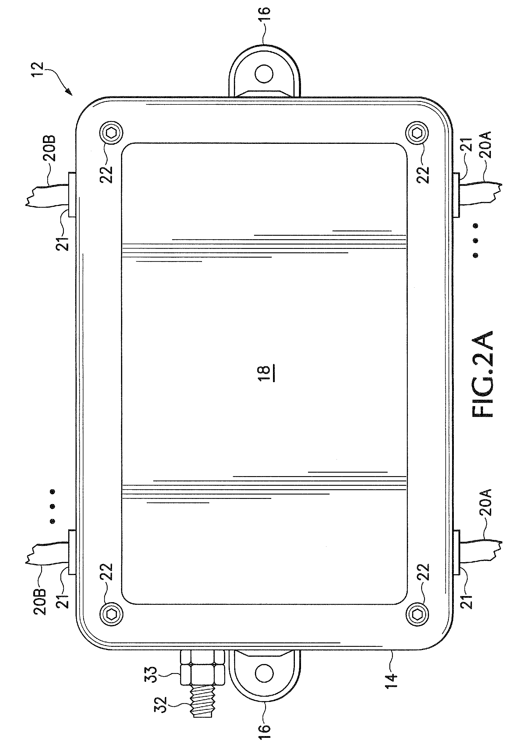
[0021]FIGS. 1 and 2A show a front and top view, respectively, of a surge suppression device 12. A back view of the surge suppression device 12 is substantially the same as the front view shown in FIG. 1. The surge suppression device 12 includes an enclosure 14 that in one embodiment is made of plastic. However, the enclosure 14 can be made out of any material including metal. Two tongues 16 on opposite sides of the enclosure 14 include holes for attaching the surge suppression device 12 to a wall.

[0022] A top lid 18 of the enclosure 14 is removable for inserting and removing individual surge suppression modules 30 shown in more detail below in subsequent figures. The lid 18 is attached to a bottom section 24 by screws 22.

[0023] The surge suppression device 12 is attached to different data cables 20 to prevent electrical power surges from damaging electrical equipment. In one specific application, the surge suppression module 12 is used to dissipate electrical power surges on telec...


PUM


Abstract

A surge suppression unit comprises connection circuitry for coupling the surge suppression unit in a communication cable. Surge suppression circuitry uses Silicon Avalanche Diodes (SADs) that couple power surges on the communication cable to ground. In one embodiment, the surge suppression unit includes multiple surge suppression modules configured for inserting into different slots in a same enclosure. The surge suppression modules can be quickly and easily inserted and then removed for connection with different communication cables

Description

CROSS-REFERENCE TO RELATED APPLICATION [0001] The present application claims priority from U.S. Provisional Patent Application Ser. No. 60 / 822,180, filed Aug. 11, 2006, incorporated herein by reference in its entirety for all purposes.BACKGROUND [0002] Surge suppressors are used to protect electronic equipment connected to a power line or data cable from voltage surges. Surge suppressors operate by providing an alternate electrical pathway having lower resistance for voltages exceeding a certain desired threshold. Providing an easier pathway for excess voltages prevents these voltage “surges” or “spikes” from traveling into and damaging electronic equipment connected to the AC circuit or data cable. Typical surge suppressors use Metal Oxide Varistors (MOVs) or Silicon Avalanche Diodes (SAD) to provide this alternate pathway. [0003] In a surge suppression assembly, the MOV or SAD surge suppression circuits are connected to a bus bar. The bus bar provides an electrical coupling betwee...

Claims


Application Information

Patent Timeline
IPC IPC(8): H02H9/04
CPCH04L12/10
Inventor WILSON, JAMES A.SULLIVAN, DANIEL J.CHADWICK, RICHARD R.
Owner A C DATA SYST INC
Learn More