Spatial modulation method and transmitting and receiving apparatuses using the same in a multiple input multiple output system

a technology of multi-input and output, which is applied in the field of spatial modulation (sm) method and transmitting and receiving apparatuses using the same in a multi-input multiple output (mimo) system, can solve the problems of parallel signal transmission experiencing more severe distortion, many challenging issues in the mimo system, and shortage of algorithms available for mimo transmission

Active Publication Date: 2008-02-14
SAMSUNG ELECTRONICS CO LTD +1
View PDF12 Cites 58 Cited by
  • Summary
  • Abstract
  • Description
  • Claims
  • Application Information

AI Technical Summary

Benefits of technology

[0010] An aspect of exemplary embodiments of the present invention is to address at least the above problems and / or disadvantages and to provide at least the advantages described below. Accordingly, an aspect of exemplary embodiments of the present invention is to provide a MIMO system for obviating the need for synchronization among transmitter antennas by activating one transmitter antenna, and not causing ISI at a receiver.
[0011] Exemplary embodiments of the present invention provide a method for increasing transmission efficiency per unit hertz using the spatial layout of transmitter antennas as information and a transmitter using the same.
[0012] Exemplary embodiments of the present invention provide a detection method for achieving a spatial multiplexing gain, while reducing the demodulation complexity of a receiver and a receiver using the same in a MIMO-OFDM system.

Problems solved by technology

Despite these benefits, the MIMO system has many challenging issues to tackle in order to increase capacity gains.
Moreover, there is a shortage of algorithms available for MIMO transmission and Inter-Channel Interference (ISI) occurs at the receiver.
While the MIMO system has an improved SNR due to a diversity gain, as spectral efficiency increases, the parallel signal transmission experiences more severe distortion.
However, since a MIMO-OFDM system suffers from high demodulation complexity for each lower-layer subcarrier, an algorithm for reducing the complexity is required.

Method used


Image

  • Spatial modulation method and transmitting and receiving apparatuses using the same in a multiple input multiple output system
  • Spatial modulation method and transmitting and receiving apparatuses using the same in a multiple input multiple output system
  • Spatial modulation method and transmitting and receiving apparatuses using the same in a multiple input multiple output system

Examples


Embodiment Construction

[0026] The matters defined in the description such as a detailed construction and elements are provided to assist in a comprehensive understanding of exemplary embodiments of the invention. Accordingly, those of ordinary skill in the art will recognize that various changes and modifications of the embodiments described herein can be made without departing from the scope and spirit of the invention. Also, descriptions of well-known functions and constructions are omitted for clarity and conciseness.

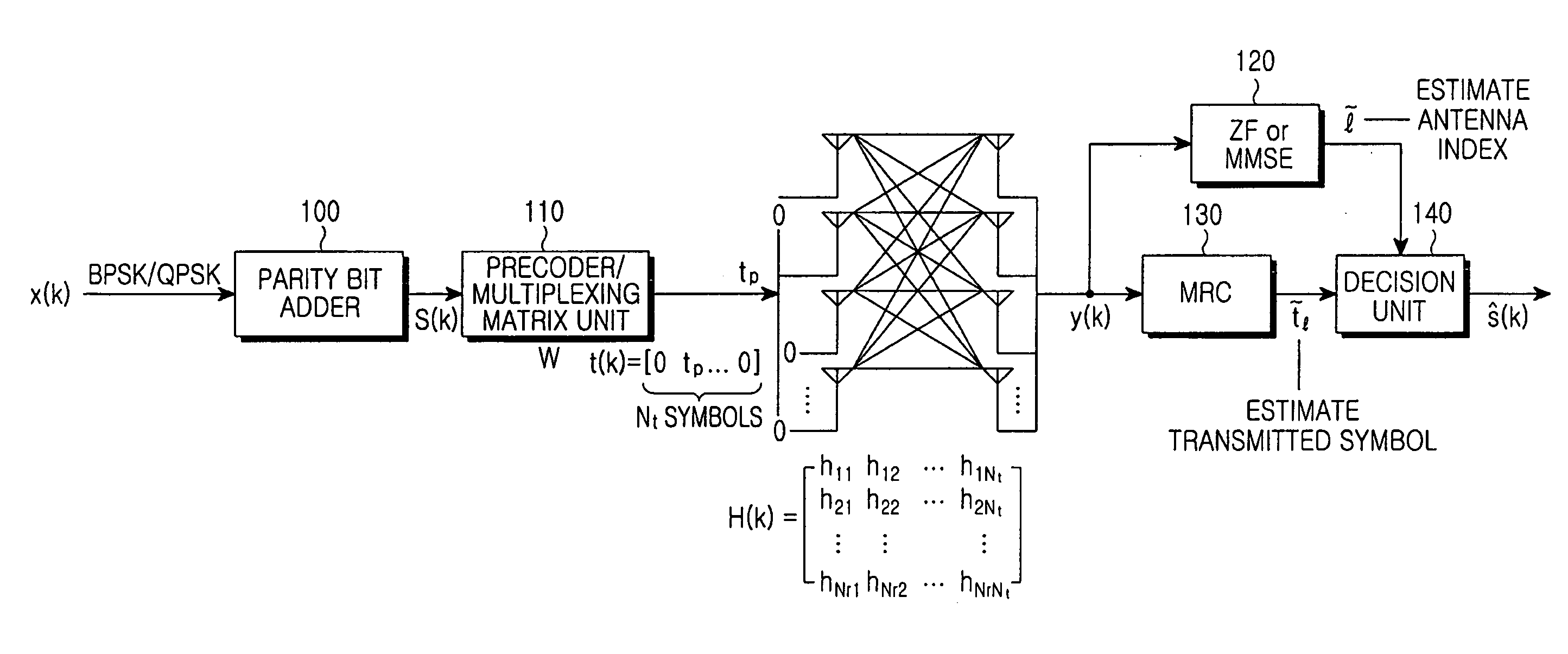
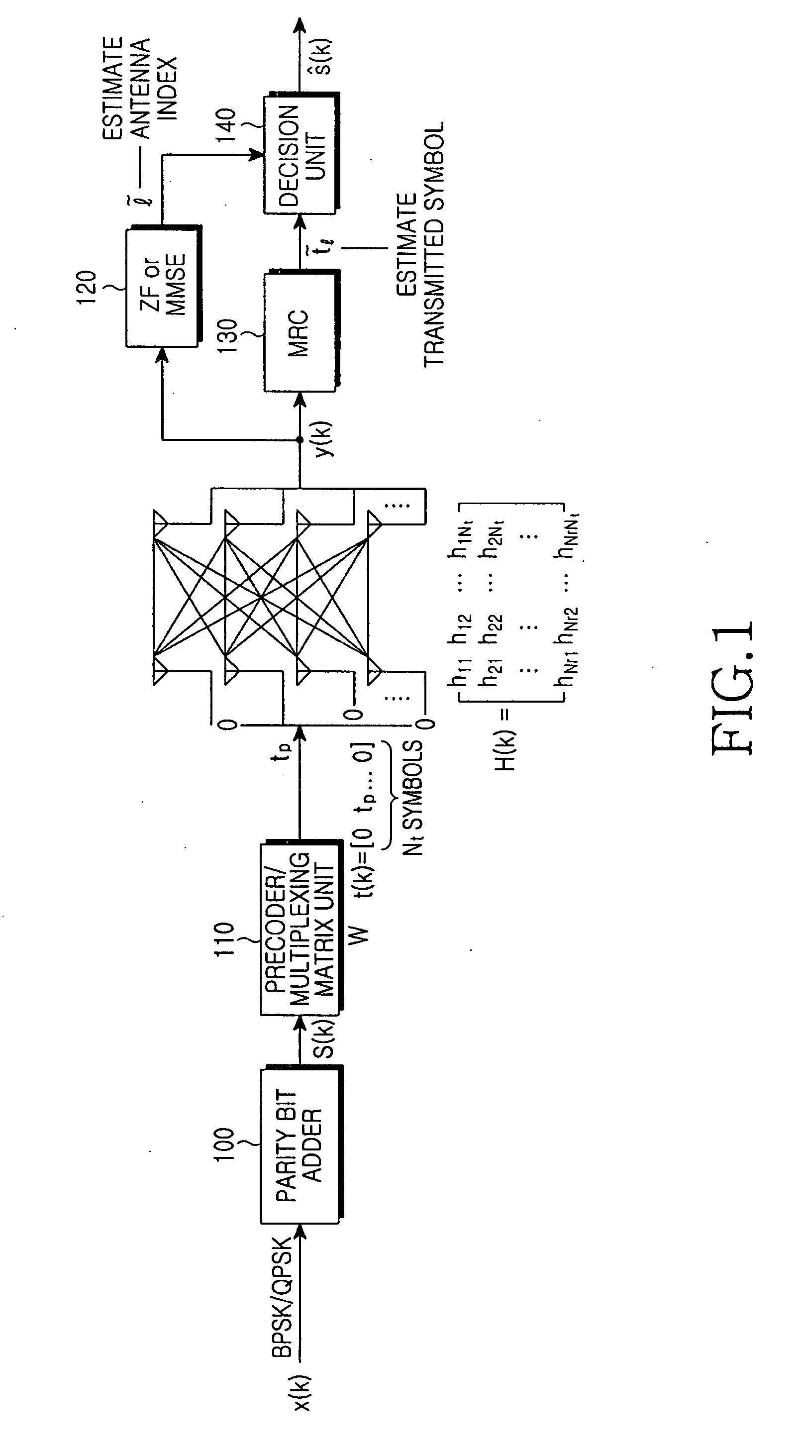
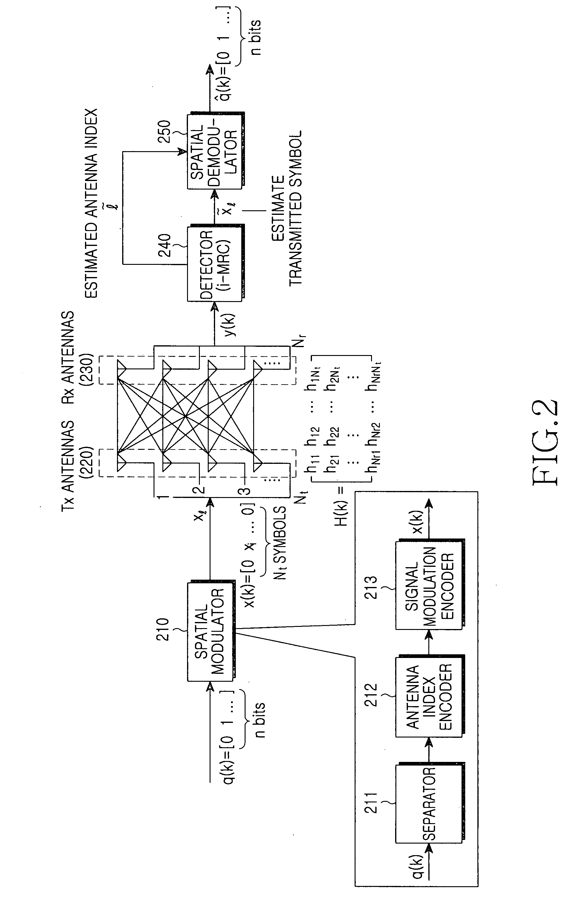
[0027] Exemplary embodiments of the present invention are intended to provide an SM method for increasing spectral efficiency. The SM method characteristically uses one activated transmitter antenna per unit time in a MIMO system, thereby not causing ICI and obviating the need for synchronization. Also, since the SM method utilizes an index of the activated antenna as an information source, it remarkably increases transmission capacity per unit hertz.

[0028] Signal Space Multiplexing (SSM...


PUM


Abstract

A spatial modulation method and transmitting and receiving apparatuses using the spatial modulation method in a MIMO system are provided. The spatial modulation method uses an index of an activated antenna and a signal modulation constellation as an information source. The spatial modulation method is applied to the transmitting apparatus. The receiving apparatus uses a spatial modulation detection method in which a channel path gain is repeatedly multiplied to detect the spatially modulated signal efficiently.

Description

CROSS-REFERENCE TO RELATED PATENT APPLICATION [0001] This application claims the benefit under 35 U.S.C. §119(a) of a Korean Patent Application filed in the Korean Intellectual Property Office on Jul. 11, 2006 and assigned Serial No. 2006-64934, the entire disclosure of which is hereby incorporated by reference. BACKGROUND OF THE INVENTION [0002] 1. Field of the Invention [0003] The present invention relates generally to a Spatial Modulation (SM) method, and transmitting and receiving apparatuses using the same in a Multiple Input Multiple Output (MIMO) system. More particularly, the present invention relates to a transmitting apparatus using an SM method and a receiving apparatus using an SM detection method based on Iterative Maximum Ratio Combining (i-MRC) in a MIMO system. [0004] 2. Description of the Related Art [0005] Over the past few years, the wireless communications field has witnessed a remarkable growth, shifting from 3rd Generation (3G) communications to 4th Generation ...

Claims


Application Information

Patent Timeline
Patent Type & Authority Applications(United States)
IPC IPC(8): H04L23/02G06F17/10H04L27/28
CPCH04B7/0413H04L1/0656H04L1/0063H04B7/0691
Inventor AHN, CHANG-WOOKYUN, SANG-BOHKIM, EUNG-SUNHAAS, HARALDRAED, MESLEHHYON, TAE-INMCLAUGHLIN, STEPHER
Owner SAMSUNG ELECTRONICS CO LTD
Why Eureka
Try Eureka