Imaging method and modality for medical application

a medical application and imaging method technology, applied in the field of imaging methods and modality for medical applications, can solve the problems of extra time for retaking the formal image, image not always correspond, and difficult especially for tomographic modalities such as ct scanners and mri scanners

Active Publication Date: 2008-02-14
FUJIFILM CORP
View PDF2 Cites 28 Cited by
  • Summary
  • Abstract
  • Description
  • Claims
  • Application Information

AI Technical Summary

Benefits of technology

[0013]According to the present invention, if the defined main scanning area does not correspond to the anatomical structure designated by the order data, a warning is given before the operator actually starts main scanning. Thus, the present inve...

Problems solved by technology

However, the captured medical images do not always correspond to the site designed by the order.
Because the position of anatomical structures differ a little between individual patients, it is difficult especially for tomographic modalities, such as CT scanners and MRI scanners, to adjust the imaging or scanning area to the ordered site...

Method used


Image

  • Imaging method and modality for medical application
  • Imaging method and modality for medical application
  • Imaging method and modality for medical application

Examples


second embodiment

[0060]Next the present invention will be described with reference to the flow chart shown in FIG. 7, wherein site recognition is carried out with respect to the whole prescanning image. In the second and following embodiments, equivalent elements to the above described elements will be designated by the same reference numerals, so the details of these elements will be omitted.

[0061]According to the embodiment shown in FIG. 7, a CPU 60 sends data of a prescanning image PI to a site recognizer 70, so the site recognizer 70 analyzes the image data to recognize respective sites contained in the prescanning image PI, in the way as shown for example in FIG. 8. Then the site recognizer 70 sends the result of site recognition to the CPU 60.

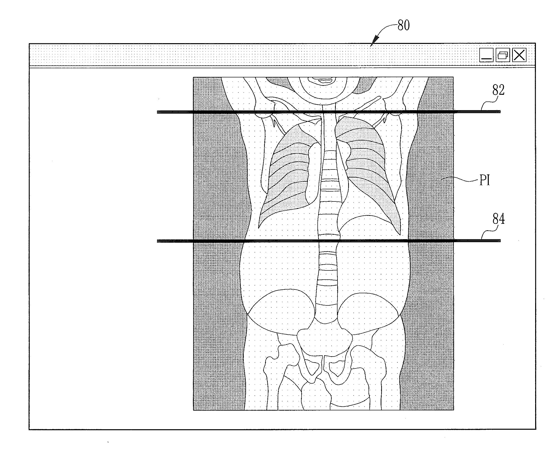
[0062]Upon receipt of the site recognition result, the CPU 60 drives a monitor 44 to display the prescanning image PI and start and end lines 82 and 84 in the same way as shown in FIG. 4, to let the operator define a main scanning area with the lines 82 a...

third embodiment

[0064]FIG. 9 illustrates an imaging method wherein site recognition is carried out with respect to the whole prescanning image, and a main scanning area is automatically defined on the basis of the recognized sites.

[0065]Specifically, a CPU 60 sends data of a prescanning image PI to a site recognizer 70, so the site recognizer 70 analyzes the image data to recognize respective sites contained in the prescanning image PI, in the way as shown for example in FIG. 8. Then the site recognizer 70 sends the result of site recognition to the CPU 60.

[0066]Upon receipt of the recognition result, the CPU 60 reads out the corresponding order data from an HDD 62 and defines on the basis of the order data and the recognition result a main scanning area corresponding to the site of inspection designated by the order data. After defining the main scanning area, the CPU 60 drives a monitor 44 to display start and end lines 82 and 84 on the prescanning image PI, showing the defined main scanning are...

fourth embodiment

[0070]FIG. 11 shows the present invention. As shown in the flow chart of FIG. 11, corresponding order data is read out from an HDD 62 immediately after a prescanning image PI is captured. Then, the captured prescanning image PI is displayed with start and end lines 82 and 84 on a control screen 80, and a window 90 is popped up beside the prescanning image PI to display information on the site of inspection designated by the order data. Thereby, the operator can pay attention to which site of inspection while defining a main scanning area by shifting the lines 82 and 84 on the prescanning image PI.

[0071]When the operator completes defining the main scanning area, a CPU 60 sends data of the prescanning image PI and setup data of the main scanning area to a site recognizer 70, and gets a site recognition result. Then, the CPU 60 judges based on corresponding order data and the site recognition result if the site in the defined main scanning area corresponds to the site of inspection de...


PUM


Abstract

A CT scanner pre-scans a patient by radiating rays of a lower amount from one direction to obtain a perspective prescanning image. An operator defines a main scanning area, in which images for medical application are to be captured, with reference to the prescanning image displayed on a monitor screen. A site recognizer analyzes data of the prescanning image to recognize anatomical structures located in the defined main scanning area. Based on the recognized anatomical structures and order data designating a site of inspection, it is judged whether the main scanning area corresponds to the site of inspection designated by the order data. If not, a warning is displayed on the monitor screen. The site recognizer may recognize all anatomical structures contained in the prescanning image, so that a default main scanning area may be defined on the basis of the recognition results and the order data.

Description

FIELD OF THE INVENTION[0001]The present invention relates to a method of capturing an image for medical application from a patient by scanning the patient in a main scanning area that is defined based on an image captured by pre-scanning the patient. The present invention relates also to a modality that captures an image for medical application according to the method of the present invention.BACKGROUND OF THE INVENTION[0002]In medical facilities, such as clinics and hospitals, a variety of modalities like those for CR (computed radiography), CT (computed tomography), MRI (magnetic resonance imaging), PET (positron emission tomography) and ultrasonography, have been widely used for capturing images of anatomical structures from patients. The images captured by these modalities are utilized for medical diagnoses, and play an important role these days.[0003]Doctors in charge of the patients, such as internists and surgeries, forward orders to a radiological department, instructing a b...

Claims


Application Information

Patent Timeline
IPC IPC(8): G01D18/00
CPCA61B6/032A61B6/0457A61B6/469A61B6/488G06T2207/30004G06T2207/10081G06T2207/10116G06T2207/20104G06T7/0012A61B6/0487
Inventor SAKAIDA, HIDEYUKIMOCHIZUKI, NAOKI
Owner FUJIFILM CORP
Why Eureka
Try Eureka